Updated answer - added github repo
Source Link
Greenonline
  • 2.8k
  • 5
  • 24
  • 36

Hopefully this is the same HAT, or at least (functionally) the same as the GeeekPi 4 channel relay hat - it looks the same...

Clone of GeeekPi 4 Channel Relay Hat Board

... and the link below also references the GeeekPi Github repository.

From EP-0099

Register Map

Register Address Function Value
0x01 Relay 1 0(FULL OFF) - 1/255(ON)
0x02 Relay 2 0(FULL OFF) - 1/255(ON)
0x03 Relay 3 0(FULL OFF) - 1/255(ON)
0x04 Relay 4 0(FULL OFF) - 1/255(ON)

Note that this is relative to the base address, which is set by jumpers:

Base address

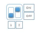
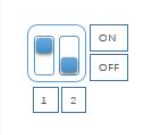
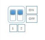
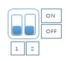
DIP switch status icon Device Address
0x10 DIP switch position 0x10
0x11 DIP switch position 0x11
0x12 DIP switch position 0x12
0x13 DIP switch position 0x13

The hat uses I2C, and so, from I2C - Inter Integrated Circuit, it uses pins 3 (GPIO2) and 5 (GPIO3) of the GPIO:

Top of GPIO bus

In addition, there is a repo with some demo code: dockerpi. In the 4channelRelay directory, the product link, on wiki.52pi.com, is broken. However, after some precise googling, the linked to product page would appear to be the EP-0099 link posted above.

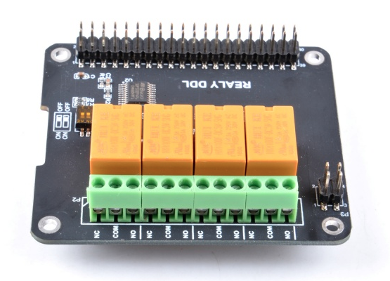
Hopefully this is the same HAT, or at least (functionally) the same as the GeeekPi 4 channel relay hat - it looks the same...

Clone of GeeekPi 4 Channel Relay Hat Board

From EP-0099

Register Map

Register Address Function Value
0x01 Relay 1 0(FULL OFF) - 1/255(ON)
0x02 Relay 2 0(FULL OFF) - 1/255(ON)
0x03 Relay 3 0(FULL OFF) - 1/255(ON)
0x04 Relay 4 0(FULL OFF) - 1/255(ON)

Note that this is relative to the base address, which is set by jumpers:

Base address

DIP switch status icon Device Address
0x10 DIP switch position 0x10
0x11 DIP switch position 0x11
0x12 DIP switch position 0x12
0x13 DIP switch position 0x13

The hat uses I2C, and so, from I2C - Inter Integrated Circuit, it uses pins 3 (GPIO2) and 5 (GPIO3) of the GPIO:

Top of GPIO bus

Hopefully this is the same HAT, or at least (functionally) the same as the GeeekPi 4 channel relay hat - it looks the same...

Clone of GeeekPi 4 Channel Relay Hat Board

... and the link below also references the GeeekPi Github repository.

From EP-0099

Register Map

Register Address Function Value
0x01 Relay 1 0(FULL OFF) - 1/255(ON)
0x02 Relay 2 0(FULL OFF) - 1/255(ON)
0x03 Relay 3 0(FULL OFF) - 1/255(ON)
0x04 Relay 4 0(FULL OFF) - 1/255(ON)

Note that this is relative to the base address, which is set by jumpers:

Base address

DIP switch status icon Device Address
0x10 DIP switch position 0x10
0x11 DIP switch position 0x11
0x12 DIP switch position 0x12
0x13 DIP switch position 0x13

The hat uses I2C, and so, from I2C - Inter Integrated Circuit, it uses pins 3 (GPIO2) and 5 (GPIO3) of the GPIO:

Top of GPIO bus

In addition, there is a repo with some demo code: dockerpi. In the 4channelRelay directory, the product link, on wiki.52pi.com, is broken. However, after some precise googling, the linked to product page would appear to be the EP-0099 link posted above.
Added image descriptions and hover tags. Fixed typos.
Source Link
Greenonline
  • 2.8k
  • 5
  • 24
  • 36

Hopefully this is the same HAT, or at least (functionally) the same as the GeeekPi 4 relychannel relay hat - it looks the same...

enter image description hereClone of GeeekPi 4 Channel Relay Hat Board

From EP-0099

Register Map

Register Address Function Value
0x01 Relay 1 0(FULL OFF) - 1/255(ON)
0x02 Relay 2 0(FULL OFF) - 1/255(ON)
0x03 Relay 3 0(FULL OFF) - 1/255(ON)
0x04 Relay 4 0(FULL OFF) - 1/255(ON)

Note that this is relative to the base address, which is set by jumpers:

Base address

DIP switch status icon Device Address
enter image description here0x10 DIP switch position 0x10
enter image description here0x11 DIP switch position 0x11
enter image description here0x12 DIP switch position 0x12
enter image description here0x13 DIP switch position 0x13

The hat uses I2C, and so, from I2C - Inter Integrated Circuit, it uses pins 3 (GPIO2) and 5 (GPIO3) of the GPIO:

Top of GPIO bus

Hopefully this is the same HAT, or at least (functionally) the same as the GeeekPi 4 rely hat - it looks the same...

enter image description here

From EP-0099

Register Map

Register Address Function Value
0x01 Relay 1 0(FULL OFF) - 1/255(ON)
0x02 Relay 2 0(FULL OFF) - 1/255(ON)
0x03 Relay 3 0(FULL OFF) - 1/255(ON)
0x04 Relay 4 0(FULL OFF) - 1/255(ON)

Note that this is relative to the base address, which is set by jumpers:

Base address

DIP switch status icon Device Address
enter image description here 0x10
enter image description here 0x11
enter image description here 0x12
enter image description here 0x13

Hopefully this is the same HAT, or at least (functionally) the same as the GeeekPi 4 channel relay hat - it looks the same...

Clone of GeeekPi 4 Channel Relay Hat Board

From EP-0099

Register Map

Register Address Function Value
0x01 Relay 1 0(FULL OFF) - 1/255(ON)
0x02 Relay 2 0(FULL OFF) - 1/255(ON)
0x03 Relay 3 0(FULL OFF) - 1/255(ON)
0x04 Relay 4 0(FULL OFF) - 1/255(ON)

Note that this is relative to the base address, which is set by jumpers:

Base address

DIP switch status icon Device Address
0x10 DIP switch position 0x10
0x11 DIP switch position 0x11
0x12 DIP switch position 0x12
0x13 DIP switch position 0x13

The hat uses I2C, and so, from I2C - Inter Integrated Circuit, it uses pins 3 (GPIO2) and 5 (GPIO3) of the GPIO:

Top of GPIO bus

Source Link
Greenonline
  • 2.8k
  • 5
  • 24
  • 36

Hopefully this is the same HAT, or at least (functionally) the same as the GeeekPi 4 rely hat - it looks the same...

enter image description here

From EP-0099

Register Map

Register Address Function Value
0x01 Relay 1 0(FULL OFF) - 1/255(ON)
0x02 Relay 2 0(FULL OFF) - 1/255(ON)
0x03 Relay 3 0(FULL OFF) - 1/255(ON)
0x04 Relay 4 0(FULL OFF) - 1/255(ON)

Note that this is relative to the base address, which is set by jumpers:

Base address

DIP switch status icon Device Address
enter image description here 0x10
enter image description here 0x11
enter image description here 0x12
enter image description here 0x13