replaced http://raspberrypi.stackexchange.com/ with https://raspberrypi.stackexchange.com/
Source Link

A Breadboard makes it easier to experiment. Here is a breadboard used to connect a LED (and current-limiting resistor) to a GPIO port on a Raspberry Pi. You'll need male-to-female jumper leads.
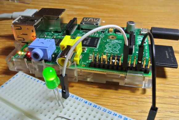
Breadboard and pi

You can get by without one if you have a soldering iron and don't mind a lot of extra work.

See also


You have to arrange the parts so that there is a "circuit", in my picture, the current flows from the GPIO pin through the white jumper-wire into column 14 of the breadboard and along that column to the anode of the LED, through the LED, down it's cathode lead into column 15, down to row f where a resistor connects to column 30 and a black jumper back to the Pi to complete the circuit.

For more about breadboards See

added 591 characters in body
Source Link

A Breadboard makes it easier to experiment. Here is a breadboard used to connect a LED (and current-limiting resistor) to a GPIO port on a Raspberry Pi. You'll need male-to-female jumper leads.

Breadboard and pi

You can get by without one if you have a soldering iron and don't mind a lot of extra work.

See also


You have to arrange the parts so that there is a "circuit", in my picture, the current flows from the GPIO pin through the white jumper-wire into column 14 of the breadboard and along that column to the anode of the LED, through the LED, down it's cathode lead into column 15, down to row f where a resistor connects to column 30 and a black jumper back to the Pi to complete the circuit.

For more about breadboards See

A Breadboard makes it easier to experiment. Here is a breadboard used to connect a LED (and current-limiting resistor) to a GPIO port on a Raspberry Pi. You'll need male-to-female jumper leads.

Breadboard and pi

You can get by without one if you have a soldering iron and don't mind a lot of extra work.

See also


You have to arrange the parts so that there is a "circuit", in my picture, the current flows from the GPIO pin through the white jumper-wire into column 14 of the breadboard and along that column to the anode of the LED, through the LED, down it's cathode lead into column 15, down to row f where a resistor connects to column 30 and a black jumper back to the Pi to complete the circuit.

For more about breadboards See

Links
Source Link
Loading
Source Link
Loading