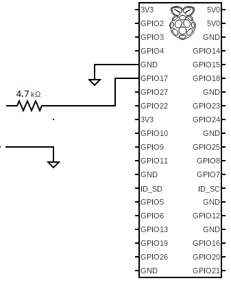
It's as simple as adding a simple resistor to limit the current flowing to the GPIO.
What we shall be carefull is to limit the current flowing "to" the GPIO, worst case when the input is 5V .
Three steps:
define the GPIO pin as input.
Add a pull_down. Thanks the BCM2836 design, each GPIO pin has an internal pull down resistor SW enabled. This pull down has a value in the range 40-100k. ([Here electrical specifications of GPIO pins][1]Here electrical specifications of GPIO pins)
This is the SW configuration of the GPIO as input with pull-down:GPIO.setmode(GPIO.BOARD) # Use physical pin numberin GPIO.setup(11, GPIO.IN, pull_up_down=GPIO.PUD_DOWN)
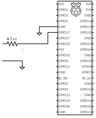
add a series resistor of 4.7k that limits current to ~0.9mA, much less than the 16mA safely supported by each GPIO pin. With this resistor the switch from logical high to logical low will happen with when the input tension falls to ~2-3V (assuming internal pull down value 40-100k). In case you want the switch happens at an higher tension you should increase the value of the series resistor, but higher resistor means lower current and more sensitivity to noise. [interface between pushbutton and Raspberry ][2]interface between pushbutton and Raspberry
[![Resistor in series to GPIO][3]][3]
References:
[1]: http://www.mosaic-industries.com/embedded-systems/microcontroller-projects/raspberry-pi/gpio-pin-electrical-specifications#rpi-gpio-input-voltage-and-output-current-limitations
[2]: https://github.com/ignaziob/MQTT-doorbell/wiki/3.-Publish-message-from-Raspberry-PI-3B
[3]: https://i.sstatic.net/ur9O5.png

