2

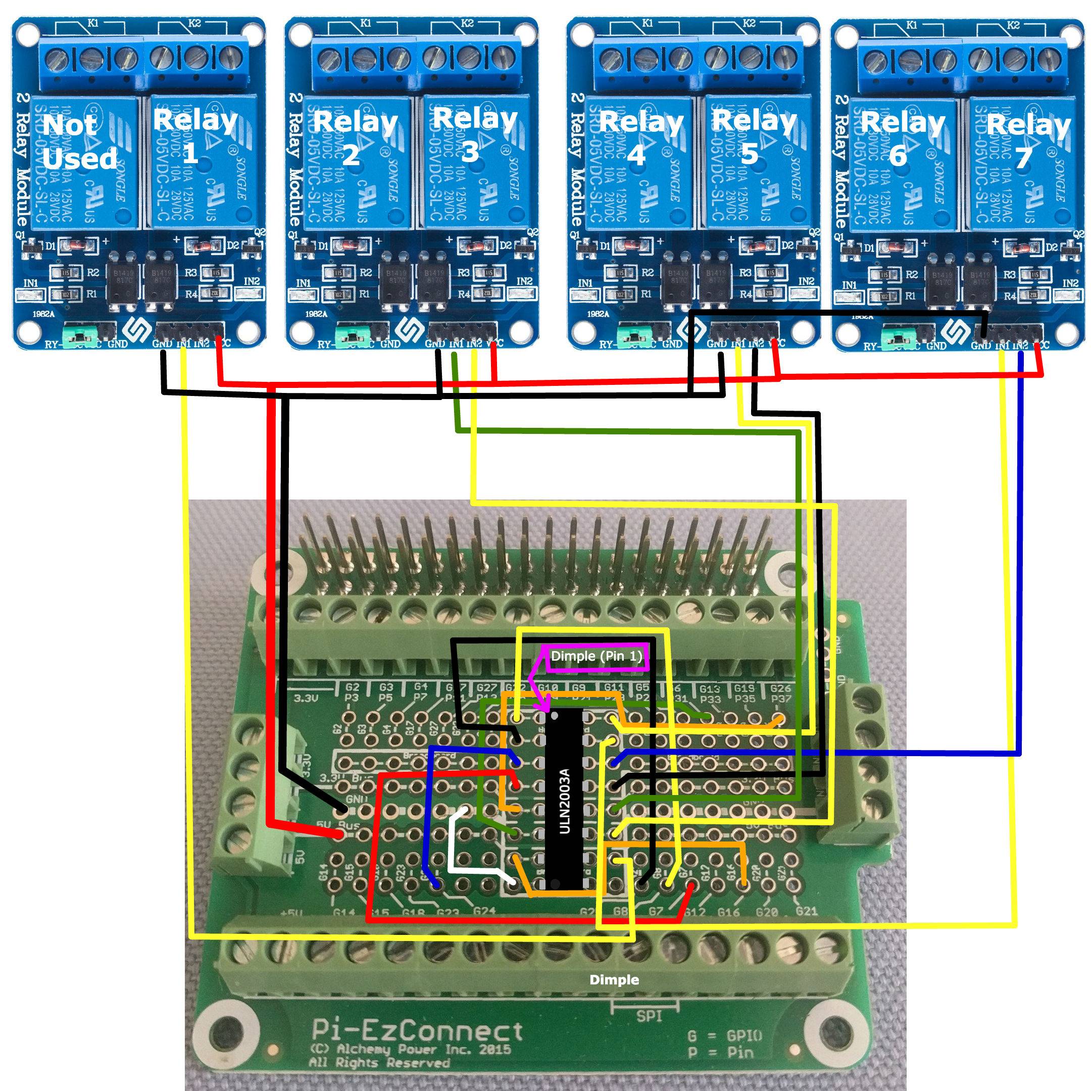
enter image description hereI have 4 Sunfounder 2 channel relays 7 of which that I'm using to control some things on my aquarium. I suspect that I may have wired them up wrong somehow though. The behavior I'm seeing is as follows;

if I open either Drain Pump/Fill Pump relay

  1. The corresponding relay opens but if the ATO relay is open, it will close.
  2. Closing either Drain Pump/Fill Pump relays has no effect on the ATO relay

If I close the ATO relay

  1. The Fish Feeder relay opens.
  2. Inversely if I open the ATO relay the Fish Feeder relay closes.

Sample code for opening and closing relays called from the command line

const Gpio = require('onoff').Gpio;    
const drain_relay = new Gpio(7, 'out');
const fill_relay = new Gpio(8, 'out');
const feed_relay = new Gpio(14, 'out');
const ato_relay = new Gpio(18, 'out');

drain_relay.writeSync(0) //closes the drain relay
drain_relay.writeSync(1) //opens the drain relay

Similar writeSync calls passing 0 to close or 1 to open the other relays are made.

These were just a couple of the anomalies I found. There could be more.
On my Raspberry Pi hat I connect the 4 pin GND to ground and VCC to +5V and IN1 and IN2 to GPIO pins. Could the signal be jumping pins on the hat? Or is there something else I'm missing?

UPDATE 6/6/18

I followed some direction that I received on the Raspberry Pi Forum here. The instruction I got was to add a ULN2003A Darlington transistor between gpio OUT and relay IN. I added this in between as instructed there. But now all relay LEDs stay on. When I command the relay open or closed the LED changes from bright to dim or dim to bright with no relay click indicating the relay itself had changed.

Update 6/8/18 8:54am EDT

Just checked voltage output between Gnd to IN1 and Gnd to IN2 pins on relay board having relays 4 and 5 at the four pin connector with the relay disconnected. Voltages were as follows; note: open and closed states are assumed because my relays aren't connected and haven't been actuated since adding the Darlington.

Relay | State | PIN | Voltage

 4    post boot  IN1     600mv
 4       Open    IN1     1.7mv
 4      closed   IN1     900mv
 5    post boot  IN2     600mv(Reset to 1.7mv post Relay 4 actuation)
 5       Open    IN2     1.7mv
 5      closed   IN2     900mv

Questions

  • Shouldn't I be seeing 5V when relays are closed?
  • If I understand correctly the relays should be closing when voltage goes to zero. Is 1.7V enough to keep the relay LED lit and prevent the relay from closing?
  • Do these seem like voltage numbers I should be expecting to see given my hardware and inputs?

Update 6/8/18 6:22pm EDT

I took the two hats off my Pi and started going through my wires looking for a loose connection or something. I found a 5v wire on my new hat that, while the solder joint looked good, the wire seemed to move pretty freely compared to the others near the solder joint.

While I was there fixing that I knew I had left a couple of the 5v and ground wires that went to the 4 pin connectors on the relay boards on my original hat when I moved the ULN2003A , the GPIO signal wires and the ULN2003A OUT to relay IN wires to the new hat. I decided to bring those 5v and ground wires over to the new hat as well. This way I have all my relay related connections on one hat and sensor related connections on the other.

After putting everything back together the relay lights no longer lit up on boot. Good!?! Maybe? My relays still weren't actuating with my commands. And now there are no changes to the LED lights. they just stay off.

I disconnected the 4 pin connectors from the relay boards and began checking them with the volt meter. I no longer had 5V across any of the VCC GND pins. But when I probed GND to IN pins and toggled the associated GPIO I still got a voltage reading between zero and 900mv.

17
  • 4
    We need a schematic and photos of the wiring.
    – joan
    Commented May 28, 2018 at 15:36
  • 2
    you might want to include the program/script you are using to control the relays. Commented May 28, 2018 at 20:08
  • 1
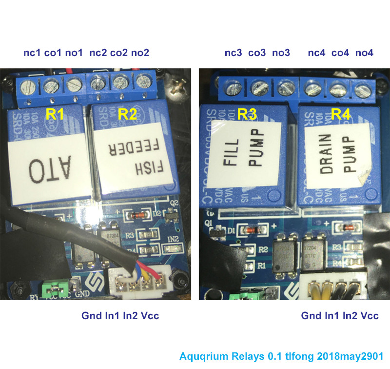
    Could you clarify A and B map to which relays (fill_pump/drain_pump/fish_feeder/ato) ? (PS: the colors used on the wiring diagram are bit confusing. typically black represents ground, red is +5V, yellow is +12V, and white/blue/green/orange etc are for GPIO signals) Commented May 28, 2018 at 21:29
  • 1
    Looking a bit closer at the wiring diagram, looks like there are 3 yellow wires, one is a ground, one goes to IN1 (fillpump) of the relay board 1 on the LHS and last one to IN2(ato) of the board on the RHS. my guess is (1) you might have swapped two signals in the actual wiring compared to the diagram (2) and/or there is some bug in the script you are using. it would help to include your script as is. Also found a relevant link that shows a RPi with this relay module you could use to test your script Commented May 28, 2018 at 21:53
  • 1
    If you want an answer you still need to add a circuit schematic, no one can tell what is happening with that maze of wires. Adding a " Darlington transistor" is unlikely to help, especially as you don't specify how it was added. The relays claim to require 15-20 mA - the GPIO can source 16mA. Using modules with Optocoupler is pointless - the relay should supply all the isolation you need. These are inappropriate relay modules; a simple module driven logic levels would be more appropriate
    – Milliways
    Commented Jun 7, 2018 at 5:55

3 Answers 3

1

In your initial diagram you do not show a GND connection to the module for Relays 6 and 7.

Lack of that ground would most likely cause the entire rest of the circuit to misbehave in deterministic ways that will show up as a definite pattern.

The existence of the pattern is a clue; not necessarily the details of the incorrect behavior itself.

To solve this problem requires eliminating points of failure and striving towards the desired outcome.

So first, check all of your wiring, correcting it as necessary

Then repeat your set of tests. Hopefully it will just work.

You'll learn something, you can be sure of that. Just writing a comprehensive test plan is an education in itself.

If there is more information that you believe would be helpful in generating answers, please come back and edit the OP so we all have a better chance of helping.

1

Your pictures don't labelled the connections. Perhaps you can let us know the wires connected to the relay modules.

Aquarium relays

Or you might to confirm if my guess below is correct.

aqua connect

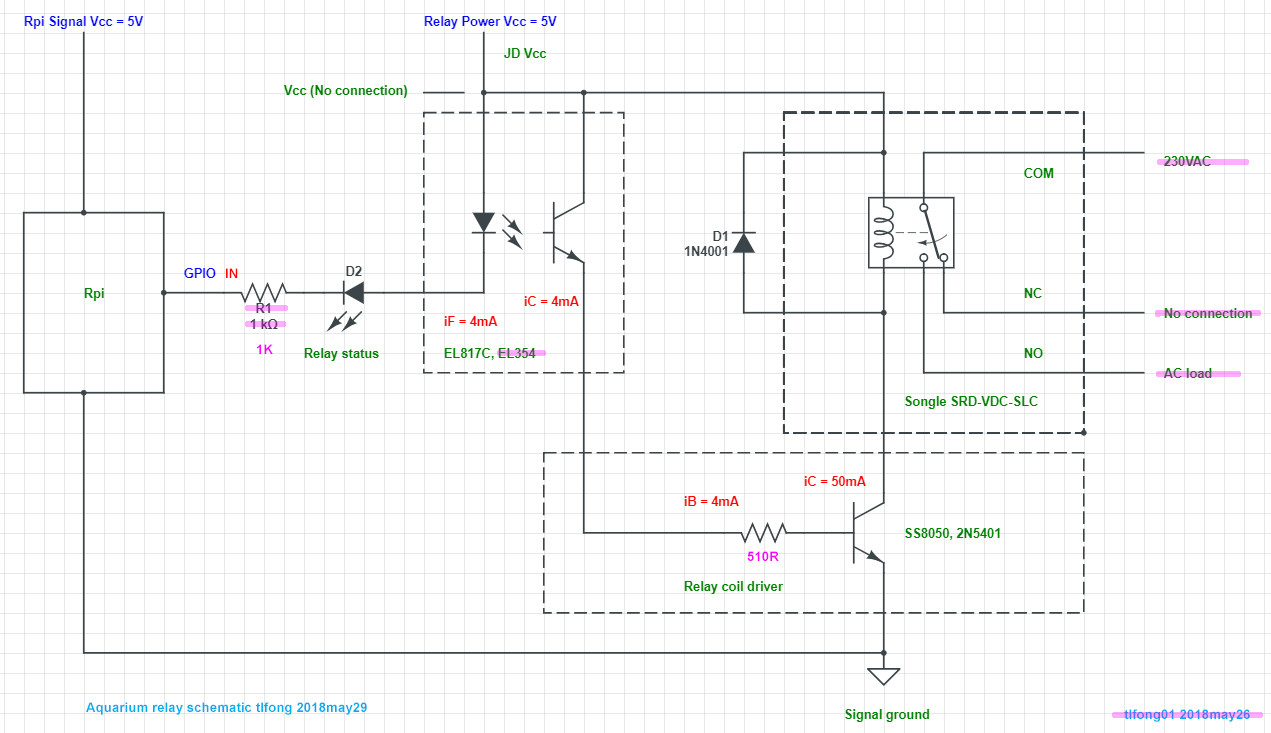
I checked your photos and found the optocoupler 817C, and the resistors 1k and 512R. So I guess your connection is something like below.

Aqua schematic

So is Step 1 below OK, Step 2 has a problem?

relay problem

In the above diagram, if GPIO is Low, relay is triggered/activated/switched "on", electrical circuit is "closed" (therefore electrical current flows), motor is switch "on".

Your "open" seems to mean my "on", your "closed" means my "off". I am still confused. Let me try again.

Do you mean that if you run the following statements:

drain_relay.writeSync(0) //closes drain relay (drain pump, drain LED on)
sleep 1 second
ato_relay.writeSync(0) //closes ATO relay (ATO pump, ATO LED switched on)
sleep 1 second

You expect drain LED turned on in Second One, then both ATO and drain LEDs turned on in Second Two. But the problem is that in Seconds Two, drain LED is turned off unexpectedly?

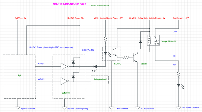
NB0109opne001 v0.3

/ to be continued, ...

Appendices

A1. SunFounder 2 Channel DC 5V Relay Module

SunFounder 2 Channel DC 5V Relay Module with Optocoupler Low Level Trigger Expansion Board for Arduino UNO R3 MEGA 2560 1280 DSP ARM PIC AVR STM32 Raspberry Pi

Relay interface board, and each one needs 15-20mA Driver Current

Equipped with high-current relay, AC250V 10A ; DC30V 10A

Standard interface that can be controlled directly by microcontroller (Arduino, Raspberry Pi, 8051, AVR, PIC, DSP, ARM, ARM, MSP430, TTL logic)

Indication LED's for Relay output status

18
  • Whether the relays are wired normally open or normally closed doesn't seem relevant to the issue I'm seeing. And the Gnd, IN1, IN2 and VCC are clearly visible on the relay boards of the first schematic image I posted.
    – Brad W
    Commented May 29, 2018 at 8:21
  • I am a bit confused. I don't know why NO and NC wiring is not irrelevant. Perhaps I missed something. Let me read you post again to find out.
    – tlfong01
    Commented May 29, 2018 at 8:56
  • OK. So for all 4 relays, you only used COM and NO. The NCs are left unconnected.
    – tlfong01
    Commented May 29, 2018 at 8:59
  • That is correct.
    – Brad W
    Commented May 29, 2018 at 9:00
  • .writeSync(0) after any relay name closes the relay allowing current to flow and "turning on" the target device. .writeSync(1) called on the same relay will open it interrupting power to the target device and "turning it off".
    – Brad W
    Commented May 29, 2018 at 15:21
0

In the beginning the problem I was having was relays actuating by a GPIO OUT signal that was not directed at them.

On the Raspberry Pi Forum user pcmanbob pointed out that my relays were designed to be actuated by 5v but the GPIO OUT signal that I was using to actuate them was only 3.3V He suggested adding a ULN2003 transistor which I soldered onto the Pi EZConnect hat shown.

This was when I went to all relays closing at boot and none of them responding to any GPIO signal. They Just stayed on.

After some breadboard testing with the ULN2003 I was able to get the relays to actuate according to the appropriate command but when I moved the setup back to the Pi EZConnect hat all relays still closed at boot.

The cause was the way the breadboard section of the Pi EZConnect solder pin holes were laid out.

Pi EZConnect layout

All pins going across the breadboard section of the Pi EZConnect are connected. Therefore the ULN2003 was being shorted/bypassed between its metal tabs across from each other.

The fix for me was to switch to a different hat with no connection between pins and make my own solder bridge between the wires and the nearest metal tab of the ULN2003.

Your Answer

By clicking “Post Your Answer”, you agree to our terms of service and acknowledge you have read our privacy policy.

Not the answer you're looking for? Browse other questions tagged or ask your own question.