1

I am using a 16x2 LCD and have it connected with MCP23017 16-bit IO port expander. To display message to the LCD, I am using Adafruit LCD library. The also have a test python code to get it working with MCP23017. I have changed the pin according to the connections I have made but it seems to be displaying only blocks in the first row of the LCD. I tried different pins, but I can't get it to work.

LCD: http://www.ebay.in/itm/16x2-Character-LCD-Module-HD44780-JHD-Black-on-Green-Backlight-Berg-Strip-/221634648684?pt=LH_DefaultDomain_203&hash=item339a745a6c

Adafruit library: https://github.com/adafruit/Adafruit-Raspberry-Pi-Python-Code/tree/master/Adafruit_CharLCD

Also I have I2C enabled on my Raspberry Pi 2

Code I am using:

#!/usr/bin/python
# Example script to show usage of MCP230xx GPIO extender to drive character LCD.

from Adafruit_CharLCD import Adafruit_CharLCD
from Adafruit_MCP230xx import MCP230XX_GPIO

bus = 1         # Note you need to change the bus number to 0 if running on a revision 1 Raspberry Pi.
address = 0x20  # I2C address of the MCP230xx chip.
gpio_count = 16  # Number of GPIOs exposed by the MCP230xx chip, should be 8 or 16 depending on chip.

# Create MCP230xx GPIO adapter.
mcp = MCP230XX_GPIO(bus, address, gpio_count)

# Create LCD, passing in MCP GPIO adapter.
lcd = Adafruit_CharLCD(pin_rs=0, pin_e=1, pins_db=[4,5,6,7], GPIO=mcp)

lcd.clear()
lcd.message("  Adafruit 16x2\n  Standard LCD")

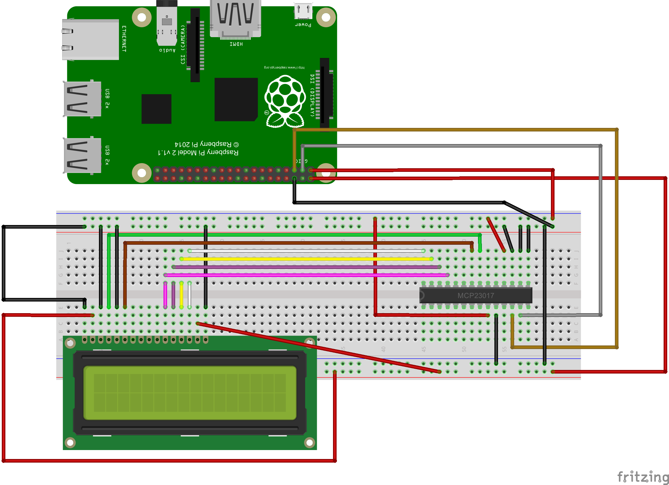
Wiring:

MCP           - PI2
SCL(Pin 12)   - GIPO0 (Pin 3)
SDA(Pin 13)   - GPIO1 (Pin 5)
VDD(pin 9)    - 3.3V
VSS(Pin 10)   - Gnd
A0(Pin 15)    - Gnd
A1(Pin 16)    - Gnd
A2(Pin 17)    - Gnd
Reset(Pin 18) - 3.3V

MCP          - LCD
GPA0(Pin 21) - RS (Pin 4)
GPA1(Pin 22) - E (Pin 6)
GPA4(Pin 25) - DB4 (Pin 11)
GPA5(Pin 26) - DB5 (Pin 12)
GPA6(Pin 27) - DB6 (Pin 13)
GPA7(Pin 28) - DB7 (Pin 14)

Also the RW pin of LCD is grounded. Below is the sketch for more clarity:

MCP23017-LCD-PI2

Any idea why this is happening or is there any step I am missing.

11
  • If it is only the top line then the display was not initialized correctly - this is the default state. You may also need to adjust the contrast either the display or the circuit should have a pot on pin 3, alternatively you can tie this pin to ground and have max contrast. To help further we are going to need to see your code and wiring - please edit your question and include these details. Commented Jul 28, 2015 at 21:03
  • @SteveRobillard Updated the question with code and wiring.
    – Prashant
    Commented Jul 29, 2015 at 14:43
  • Have you verified the that the Pi can see the MCP on the bus (learn.adafruit.com/adafruits-raspberry-pi-lesson-4-gpio-setup/…)? Commented Jul 29, 2015 at 14:46
  • Maybe your LCD needs a 5V supply? The Ebay page says so. Adafruit's tutorial mentioned that you may have to connect Vdd to 5V.
    – Frepa
    Commented Jul 29, 2015 at 14:48
  • @Frepa Tried that as well, but no luck! LCD is connected to 5v.
    – Prashant
    Commented Jul 29, 2015 at 14:51

1 Answer 1

1

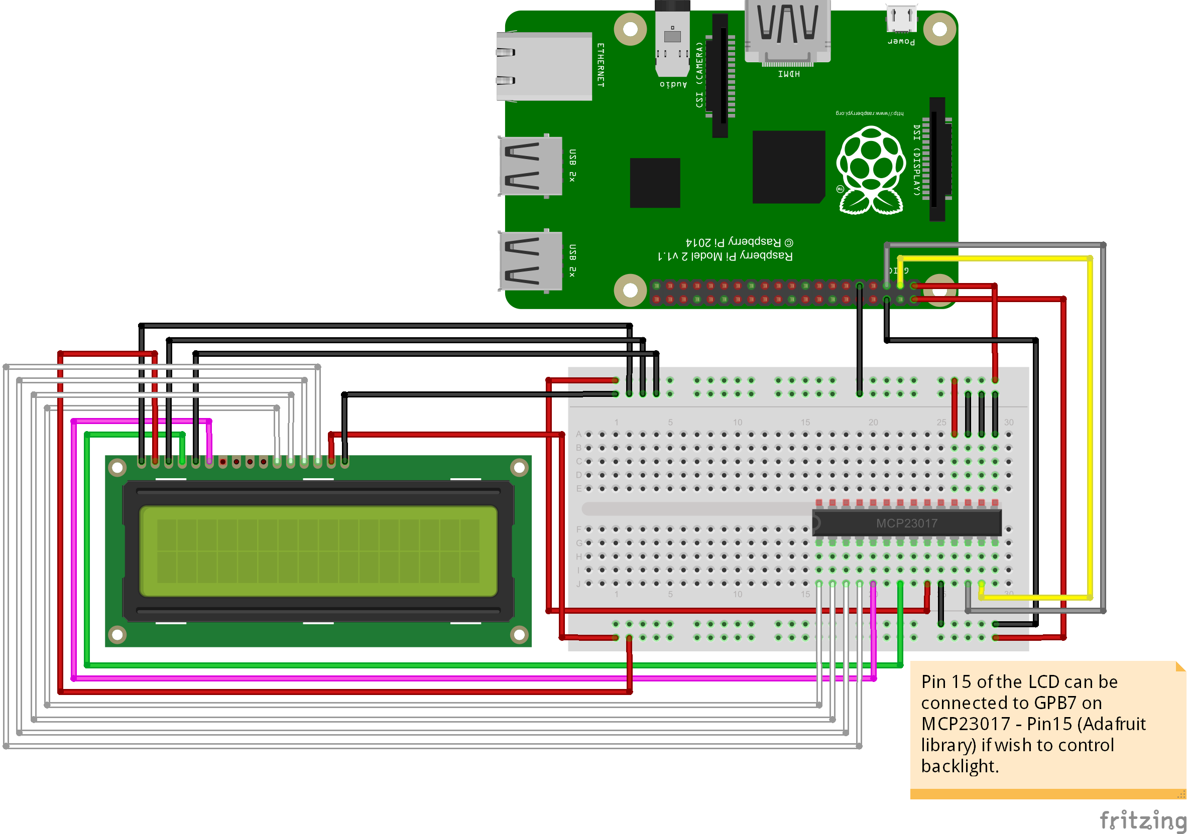
This problem is all about setting the correct pin number. In my case there were 2 things that happened. First, the jumper wire I am using is faulty and the second thing was the wiring was not proper. This is the final wiring I have now. This works well with Adafruit CharLCD library.

enter image description here

Code:

#!/usr/bin/python
import Adafruit_CharLCD as LCD
import Adafruit_GPIO.MCP230xx as MCP

#assuming i2c address is 0x20 and bus address is 1
gpio = MCP.MCP23017();

#replace None with the pin number if you want to control backlight
lcd = LCD.Adafruit_CharLCD(14,12,8,9,10,11,16,2,None,gpio=gpio)

#turn on the LCD backlight
#lcd.set_backlight(0)

lcd.clear()
lcd.message('This is a test msg')
3
  • Could you please explain how do you know which bits to use in LCD.Adafruit_CharLCD? I have a problem with using LCD with MCP23017 with Pi4J: raspberrypi.stackexchange.com/questions/87558/…
    – Alex
    Commented Aug 4, 2018 at 16:49
  • @Alex: I remember following this article: learn.adafruit.com/….
    – Prashant
    Commented Aug 7, 2018 at 6:39
  • it is still makes no sense for me. I used MCP23017 pinouts from this doc: ww1.microchip.com/downloads/en/DeviceDoc/20001952C.pdf. For example 4 white wires on your sketch connected to first four contacts on MCP23017. So it will be #1 or #15 (depends on how to rotate). But you have no 1 or 15 in your code. I know Im wrong with my understanding but not sure where exactly.
    – Alex
    Commented Aug 7, 2018 at 20:59

Your Answer

By clicking “Post Your Answer”, you agree to our terms of service and acknowledge you have read our privacy policy.

Not the answer you're looking for? Browse other questions tagged or ask your own question.