I would like to control (switch) some 12V DC motors using the GPIO pins. I do not have (or want to use) an expansion board. Nevertheless, I think this should be possible using a transistor switch (and some resistors). So, assuming an external 12V DC power supply and motor, what is the best (and safest) way to wire a control circuit to the GPIO pins, and exactly what kind of transistor should I use? In the first instance I'm interested in relatively low power motors (say, 12W/1A), but could be interested in higher power motors in the future.
2 Answers
Easiest for one direction is to use a logic level mosfet. No resistors needed
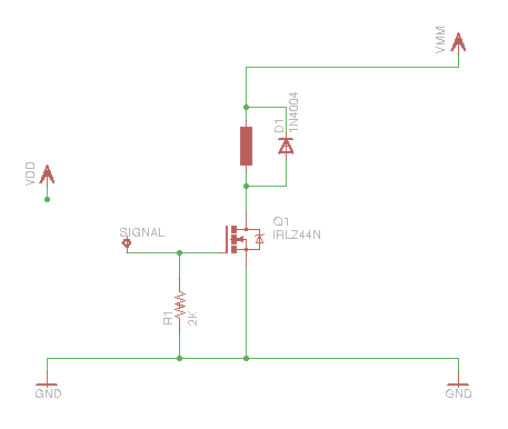
Here is a basic circuit from the ardiuno.cc forums

The IRLZ44N may be overkill for your motor, but still isn't very expensive and will work ok even if the motor is stalled. Also remember that the stall current might be 10A or more.
Many of the cheaper/less powerful parts are surface mount.
The diode(D1) is there to prevent the back EMF from the motor from damaging Q1
The resistor(R1) is there to make sure the IRLZ44N is turned off if the signal is floating. I'm not sure what the GPIO startup state is - the resistor may not be needed.
If you want to be able to reverse the motor, you should use an H-Bridge
As you go to higher power motors, you will find that big mosfets have less sensitive gate, so you'll need a driver between the GPIO and the gate to make sure the mosfet is turned on hard enough
If you just want a simple board which you can plug in, have a look at PicoBorg. It is rated for 12v / 2.5A motors, which would at least cover you initially.
It provides a circuit with a pull-down resistor, n-channel FET and diode much the same as shown in the other answer, replicated 4 times to allow control of 4 motors, one of which is attached to the PWM capable GPIO pin allowing for more control to one of the motors.
The main limitation is that it is only capable of driving motors in a single direction.
FETs used
The FETs are N channel avalanche rated logic level transistors, VDS = 20 V, RDS approx 0.023 ohms, Max 0.5W dissipation, ID = 2.9A Max at low temp 3.7 Amps
Diodes used
The diodes are SS26 Schottky diodes, VRRM Max = 60V (reverse voltage), IF(AV) = 2A (forward current), VF max = 700mV (max forward voltage), IFSM Max >=50A (max surge current)
-
I understand that this is your own product, which is fine. However, this could be a much better answer if you elaborated on why the PicoBorg is a good solution to this problem, instead of just posting a link.– JivingsCommented May 16, 2013 at 17:35
-
It is not really a better or worse solution then the previous answer, the circuit is basically the same as gnibbler's answer x4, I was just putting it out there as an alternative for those who do not fancy soldering or breadboarding themselves– PiBorgCommented May 16, 2013 at 18:03
-
That's cool. Your updated answer is much more worthy of my upvote.– JivingsCommented May 16, 2013 at 23:52
