Question
How can Rpi4B python UART talk to XY PWM Signal Generators?
Answer
Contents
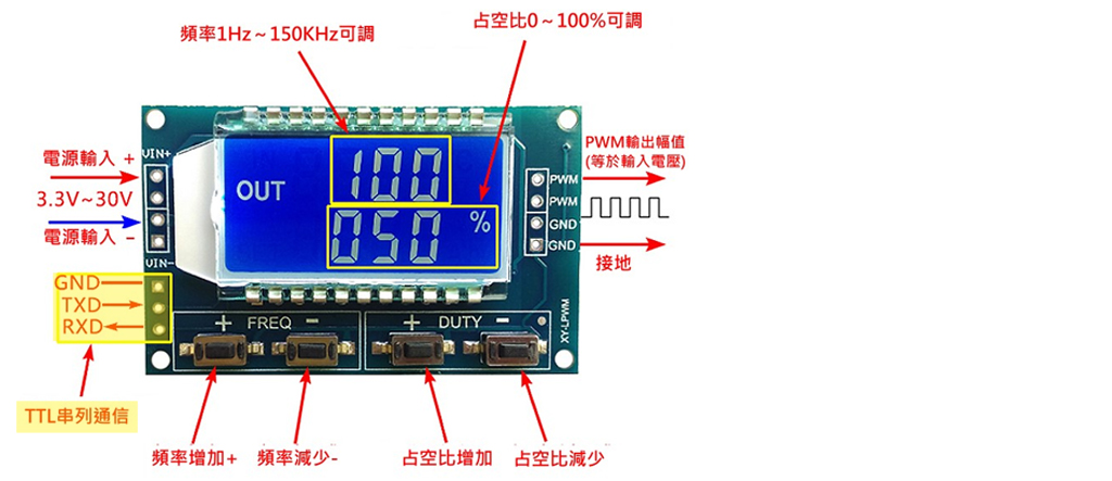
(1) Introducing XY-LPWM, UART support version of XY-PWM
(2) Using Win10 RealTerm terminal emulator to serial/UART talk to
XY-LPWM
(3) Using Rpi python program to serial/UART talk to XY-LPWM
(2) Using Win10 RealTerm terminal emulator to serial/UART talk to XY-LPWM
I am now using Win10 RealTerm terminal emulator to talk to XY-LPWM. The serial parameter setting is the following:
9600, N81 (9,600 baud, No parity, 8 data bits, 1 stop bit)
(a) I first did the RealTerm loop back, shorting TxD to RxD, and make sure any characters typed at the keyboard or send by RealTerm will be looped back / echoed at the RealTerm screen.

(b) Then I connected Win10 RealTerm USB to serial adapter/cable to the XY-LPWM sig gen as show below:
--------------------------
Win10 USB Serial   XY-LPWM
--------------------------

TxD                 RxD

RxD                 TxD

Gnd                 Gnd

---------------------------
Then I send commands
(1) "F010 to To set frequency 101Hz,
(2) "read" to read back "F010", "D050" confirming everything OK.
The two commands and response are displayed below:

/ to continue, ...
(1) Introducing XY-LPWM, UART support version of XY-PWM
The OP's sig gen is XY-PWM, which does not support Serial/UART communication/control. There are other versions of XY-PWM which support Serial communication, Examples are (1) XY-LPWM (Ref 1), (2) XY-KWPM (Ref 6).
I have been using the following "XY-LPWM" sig gen for a couple of years. This is
the only cheap, hobbyist grade square wave signal generator I know that has both manual and software / UART control.
The manual control interface is very user friendly. You press frequency up button, frequency goes, up. Similarly for frequency down button and duty cycle up and down buttons.
I used a scope to check the waveform and found it steady, at least for low frequency range from 1kHz to 10kHz. Actually other analog sig gen like NE555 astable, or Rpi master clock divided software PWM signal, can not be compared with the very precise dedicated mcu processed signal. As the signal is actually generated by a MCU (Nuvoton H78E003), so UART control should be easy, though I have not tried it. I googled and found a couple of Arduino UART programming example controlling this XY-LPWM sig gen. It should be easy to convert the Arduino UART program to Rpi.
Actually I bought the sig gen from TaoBao, which is always cheaper than AliExpress or Amazon. AliExpress and Amazon usually include the reseller's brand name. But this Taiwan based model is OEM, there is no distributor name, except the model number "XY-LPWM".
So you google with search keywords "XY-LPWM" + "AliExpress" + "Amazon" + "PWM" + "signal Generator", you should find it.
PS - The two MCUs used are from Holtek (HT1621B), and Nuvoton (H78E003A120). You may like to check out their new sig gen and other updated products (Refs 2, 3).

References
(1) XY-LPWM 1Hz-150KHz Signal Generator PWM Module
(2) Holtek Semiconductor
(3) Nuvoton Technology
(4) HT1621 RAM Mapping 324 LCD Controller for I/O MCU Datasheet
(5) Nuvoton H76E003 mcu datasheet
(6) AliExpress (UART support) XY-KPWM Signal generator 1 channel 1Hz-150KHz PWM pulse frequency duty cycle module adjustable LCD display - US$3.6
(7) XY-LPWM Sig Gen English Manual
Appendices
Appendix A - XY-LPWM sig gen pair calibration record


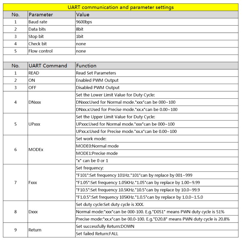
Appendix B - XY-LPWM sig gen user guide with serial communication instructions

UART communication and parameter settings
1. UART parameter setting: TTL 9600, N, 8, 1
2. Set PWM frequency:
'F101' :Set frequency is 101Hz.' 101' can by replace by 001~999;
'F1.05' :Set frequency is 1.05KHz.' 1.05' can by replace by
1.00~9.99;
'F10.5' :Set frequency is 10.5KHz.' 10.5' can by replace by
10.0~99.9;
'F1.0.5' :Set frequency is 105KHz.' 1.0.5' can by replace by
1.0.0~1.5.0;
3. Set PWM duty cycle:
'DXXX': Set duty cycle is XXX. ' XXX' can be 000-100.
Example: 'D051' means PWN duty cycle is be set as 51%.
4. Read set parameter:
Send 'read' and then get parameter.
5. Return value:
Returns 'DOWN': Set success.
Returns 'FALL': Set fail.
Appendix C- XY-KPWM Sig Gen Spec and UART user guide
AliExpress (UART support) XY-KPWM Signal generator 1 channel 1Hz-150KHz PWM pulse frequency duty cycle module adjustable LCD display - US$3.6
Features:
- UART support
- Frequency range (Normal mode): 1Hz ~ 150KHz;
- Frequency range (precise mode): 1Hz ~ 15 KHz;
- Frequency accuracy: 2%;
- Accuracy of the duty cycle: 1% in Normal mode;
- Accuracy of the duty cycle: 0.1% in accurate mode;
- Service cycle range: 0.00% -100%;
- Output current: approximately 5-30mA;
- output amplitude: identical to the input voltage;
XY-KPWM UART User Guide

End of answer


