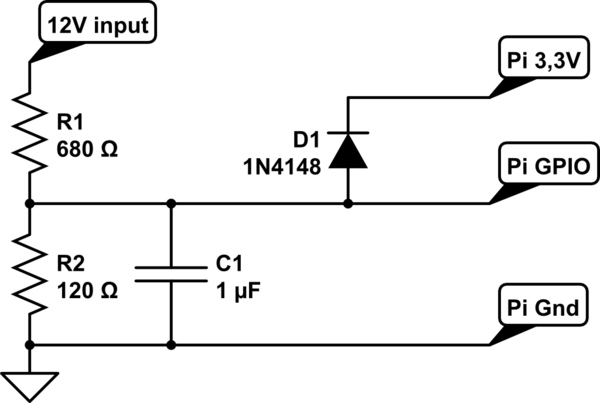
One of my experiments has lead to two seemingly dead GPIO pins on my Raspberry Pi Zero WH. I'll explain what I did to seemingly cause this; please help me understand what happened.
The goal: Have a 12V power source convert to a 3V3 signal, plugged in to a GPIO pin that is set as an input. When the 12V is present, the converted 3v3 will bring the GPIO pin high.
Background: This is for a car project. Essentially when I press the brake pedal, a certain wire (brake lights, cruise control override, etc) has 12V. I want my Raspberry Pi to be able to sense when I press the brake, so I need to lower the 12V from the brake light wire to a 3v3 converter that signals a GPIO input pin.
Application: I picked up this 3V3 converter and as a test, I set GPIO pin 17 as an input pulled down. The Raspberry Pi was plugged in to a USB 12V to 5V converter and plugged into a 12V battery. The 3V3 converter was fed by the same 12V battery, and was outputting about 3.2 Volts when I tested the output leads with my multimeter, so far so good. Because they all share the same ground, I just plugged the positive 3v3 lead from the converter into GPIO pin 17.
What went wrong?: For some reason, instead of pulling GPIO 17 high as it should have, and giving me a high signal, it was still calling GPIO 17 "Low". Hm? Then I tried again on GPIO 21 and the same thing happened. Now coincidentally, both GPIO 17 and 21 not only don't seem to read inputs correctly anymore, but they don't output either, so it seems like the pins are just dead now. Why?
A little more background: What's more confusing to me is I have done this same exact concept before on a different RPi Zero WH, and it seems to work flawlessly. In my other application, I have a 3V3 signal that I tapped directly from my PC's power supply, and I plugged the 3v3 OUTPUT from my PSU directly to GPIO pin 21 on the RPi. In Python, I pull GPIO 21 LOW, and when I turn the computer on and the PSU is outputting 3v3, GPIO will read HIGH. When the computer is off and the PSU is not outputting 3v3, GPIO 21 stays LOW. Perfect.
I'm basically doing the same exact thing here, so why did it fry the pins in the other case?
The only difference in the way I wired these was, because the PSU 3v3 was a completely separate circuit, I plugged both the positive and ground from the PSU to the RPi header board, 3v3 + to GPIO 21 as an input, and the PSU ground to Rpi ground.
In the other case, both the 5V and 3V3 sources from the converters, as well as the 12V battery powering those converters, already all share the same ground. So logically I figured the ground from the 3v3 converter was not necessary to tie into the Rpi ground because there would already be continuity, so only the positive 3v3 lead from the converter was necessary. Am I correct here, or could this possibly have something to do with it? That is the only difference I can think of between the way I wired the two, otherwise the scripts and fundamentals seem identical.
Analog vs Digital Voltage?: One final detail, I have seen people refer to analog vs digital signals before, but as far as I know, the voltage is what it is, any 3v3 signal should trigger a high signal on a GPIO input right? Is there such thing as digital and analog 3.3 volt signals? The only reason I ask is because my power supply is advertised as a "digital power" supply, so I wonder if somehow the 3V3 being output by my PSU is somehow different than the 3.2V created by the converter coming from the 12V source.

