I've been searching around for a few days and couldn't find a solution to this problem. I'm using the pgpio library that is native to the RPi4 and been looking all over their website: http://abyz.me.uk/rpi/pigpio/cif.html
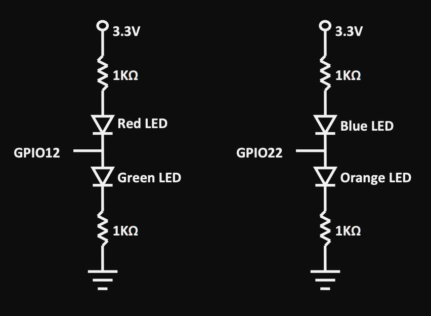
This is the circuit diagram; it is extremely simplistic. We are supposed to be using key-presses to turn on the LEDs, which is simple to implement. You can see here by the circuit diagram, if the GPIO pin is low then the Red or Blue LED will be on and if it is high then the green or orange will be on. The problem gets more complex when we need to turn both off or turn both on. So the solution to the former is sending a square wave. I was able to do that with the pigpio library; my problem now is that when one square wave is sent to say GPIO pin 12, and then the blue led is turned on and then the orange, I send a square wave to gpio pin 22 and then it doesn't work.
I've been reading that this is something that may have not been done before, but I'm not too sure.
Here is a snippet of my code:
int createSquareWave(int gpioPin){
  gpioPulse_t *squareWave = (gpioPulse_t *)malloc(sizeof(gpioPulse_t) * 2);
  squareWave[0].gpioOn = 1 << gpioPin;
  squareWave[0].gpioOff = 0;
  squareWave[0].usDelay = 15;

  squareWave[1].gpioOn = 0;
  squareWave[1].gpioOff = 1 << gpioPin;
  squareWave[1].usDelay = 15;
  gpioWaveAddNew();
  gpioWaveAddGeneric(2, squareWave);

  int waveId = gpioWaveCreate();
  return waveId;
}
When both LEDs are turned on this function is called to create the square-wave and it is sent like this:
waveId = createSquareWave(12);
gpioWaveTxSend(waveId, PI_WAVE_MODE_REPEAT);
Not sure if anyone has any ideas going forward.
Thanks!

