0

I bought the Canakit, which comes with all the necessities:

  • breadboard

  • the T-Shaped GPIO to Breadboard Interface Board

  • Wires

  • LEDs

  • and other useful things.

As soon as I opened my kit, I immediately put the raspberry pi into the case that came with it. I then plugged it up to my HDTV, both power and HDMI. I installed the Raspberry Pi OS, checked things out; it is a working computer.

Next, I went to the internet for tutorials, because frankly I have no experience will electrical engineering, the most that I know is that there is a positive and a negative, and there is various jargon such as amps, volts, and watts that I do not understand.

I followed the tutorials to the T and still, I cannot for the life of me get any damned LED to light up! Nothing happens whatsoever no matter what I try.

I did, however, somehow manage to cause a short that restarted my Pi, but the Pi continues to function normally. What could have happened? Do I need a new breadboard, new interface board, new Pi?! I've been pulling my hair out just trying to get my feet wet in the electronics field.

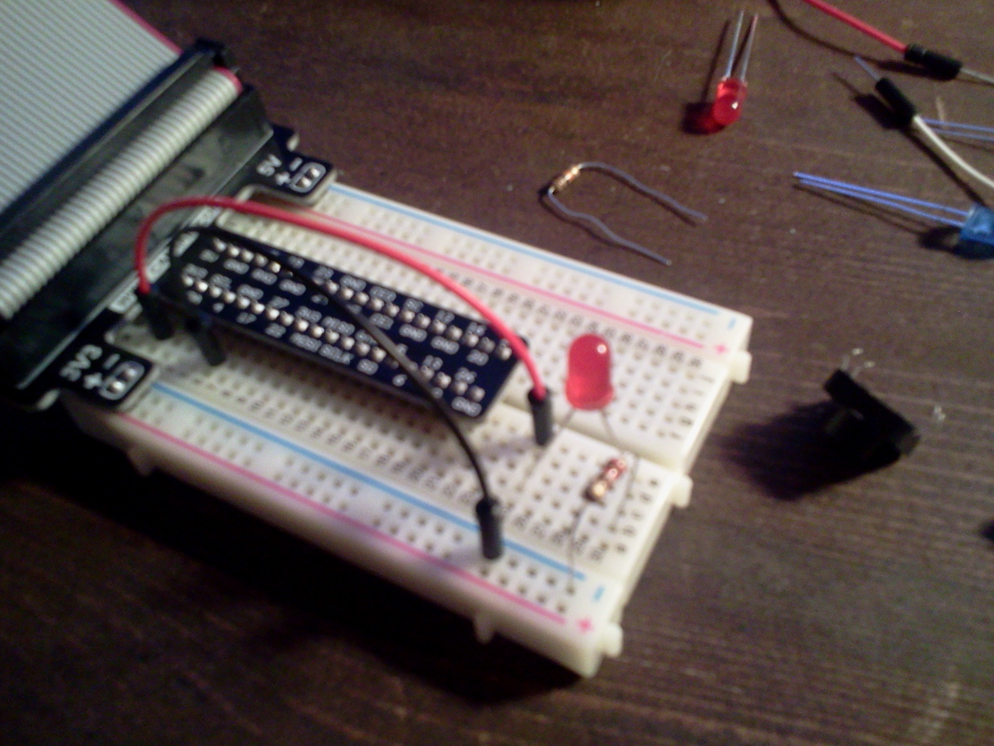
Here is my setup, please excuse the image quality.

Note: the Pi is on and running the OS fine from when I took the picture.
farview enter image description here

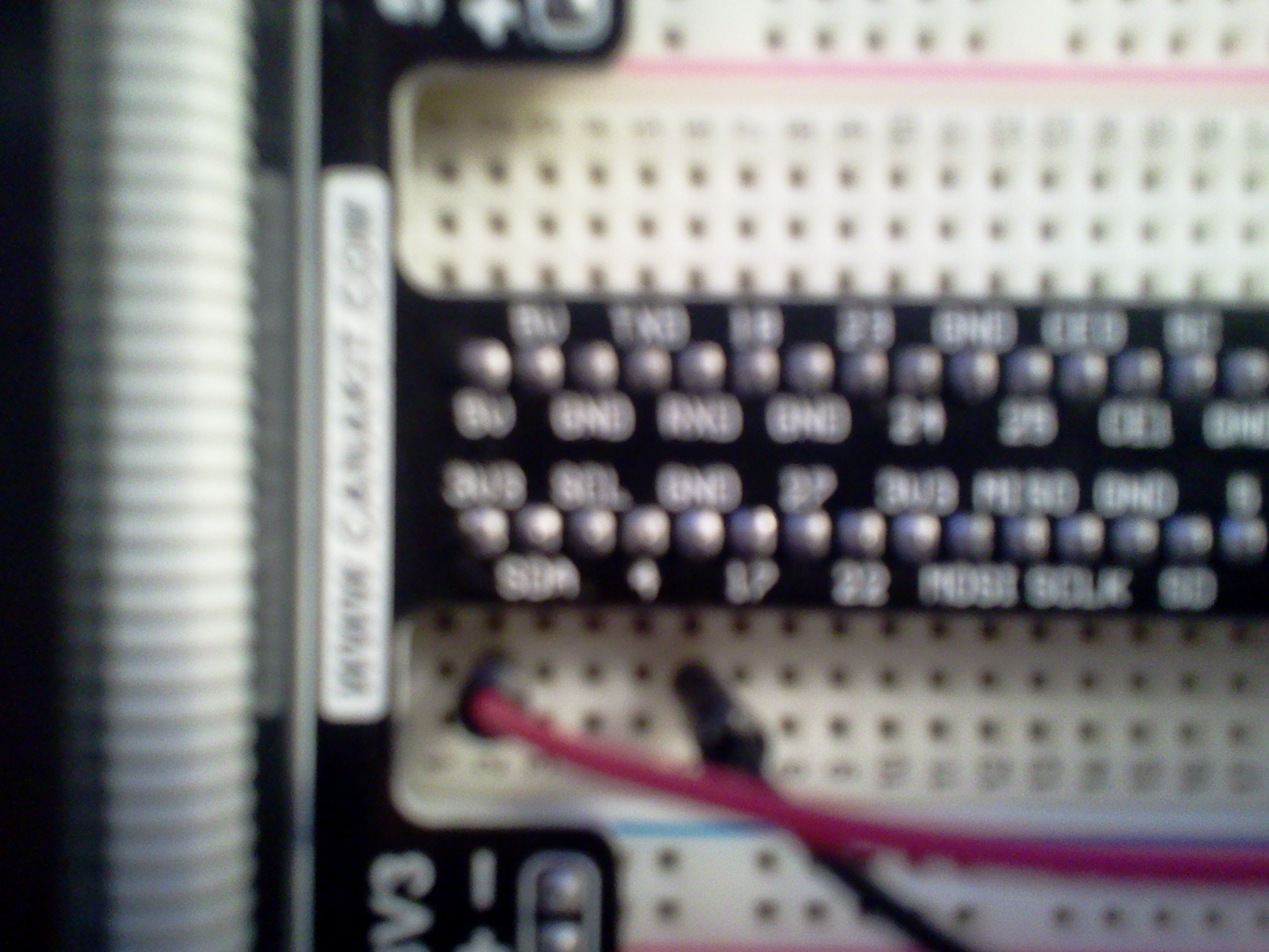
As you can almost see, I have the red cable plugged to "3V3" and I have the black cable plugged to "GND"

From where I plugged the other end of the black cable I have a resistor, of which I do not know the amperage, connected to the same rail as I have the negative side of the LED. The short end.

And I have the red cable going straight to the same rail as the positive part of the LED. This should work from what I have seen on the internet, but I can't seem to succeed.

Nothing I try works, but..

I am able to turn the PI off

if I connect the SC pin to a ground, the pi cold restarts. I know this is probably not good for the Pi, about the same as cold restarting your pc is.

But the fact that it does that tells me that the interface board actually works, or at least that one SC pin does.

Did I break something?

3
  • You should double check the connections to ensure your LED is connected the right way around (long leg is positive) with a resistor to limit the current. Are you able to attach a picture of your setup? Commented Jan 13, 2015 at 0:30
  • See pictures added.
    – dockeryZ
    Commented Jan 13, 2015 at 0:54
  • You can use the rails on the side of that breakout -> breadboard instead of the individual GND and 3.3V pins. In the pic you've jumped GND to the - half of the rail -- they're the same thing. So harmless, but you should be careful and make sure you are clear on these things because you could break something!
    – goldilocks
    Commented Jan 13, 2015 at 2:57

1 Answer 1

1

Aha, I got it to light up!

I was just searching through Google images and found this http://pi4j.com/images/gpio-control-example.png

I don't know why that it turned on this way though?

Because I had the ribbon cable plugged in backwards

If their diagram for the pins is correct, then this is my working setup

I guess the longer side is the ground, because that's what it is plugged to.

Again, I have the short side of the LED plugged into where the positive charge is.

Update

Well, I somehow manage to screw it up. I had it lit up just fine. I actually managed to figure out that I only needed one wire, from Pin 11 to a resistor connecting to the short pin on the LED; and I plugged the long pin into the apparently already grounded 3.3V side of the board. I then got trigger happy and became curious as to which pins I get get power from.

As it turned out, I was only able to get actual power to the light from only pins 11 & 35.

I am not sure which pin I chose next, but it did a cold shutdown on my pi, it did not come back on. When I touched that same aforementioned pin again, it came back on.. as if I hit the power button.

But I could never get the LED to light up again!

I touched the wrong pin somehow and now I can't seem to do anything. If I hit that same aforementioned though, it will cut shut it down as well as turn it back on.

What in the world have I done?

3
  • In your photo, you have 3.3 V direct to the LED then the resistor between the LED and ground. That's wrong -- as per your diagram linked here, the resistor should be between 3.3 V and the LED, then the LED is direct to ground. That probably won't prevent the LED from lighting up, but it may cause it to burn out...
    – goldilocks
    Commented Jan 13, 2015 at 2:52
  • Right, I switched that and my led lit up, now, unfortunately, it seems I got to trigger happy with my wires and I cannot get it to light up again. I have tried a different wire, resistor and LED. No avail.
    – dockeryZ
    Commented Jan 13, 2015 at 3:35
  • You should check the voltage on the 3.3 V rail with a multimeter (if you don't have one, you can get them at a hardware store for ~$15). You have to be careful not to short that to ground, etc. You can permanently damage things, which I guess you may have already done :(
    – goldilocks
    Commented Jan 13, 2015 at 10:52

Your Answer

By clicking “Post Your Answer”, you agree to our terms of service and acknowledge you have read our privacy policy.

Not the answer you're looking for? Browse other questions tagged or ask your own question.