5

I'm building an alarm system and I'm using a magnetic door sensor, conected to ground and a pin of the gpio set up with an internal pull-up resistor.

As far as I know, this means that the pin will be held to "up" (ie. a logical "1", voltage around 5V), and when the magnetic sensor is closed, connection will be grounded, given as a result a logical "0".

I already have this working. What I don't understand is why don't I need to put a current limiting resistor in series with the magnetic sensor.

A magnetic door sensor is nothing more than a switch, so when the door is closed, wouldn't that result in a short circuit, with current flowing from the pulled-up pin to ground, thus allowing "infinite" current to flow? (Given there are no resistors in the way).

Edit: wiring is the same as this tutorial.

Thanks!

3
  • Can you post how you have it wired? You are correct that without the limiting resistor you will draw too much current and could eventually burn something out. Are you following this learn.adafruit.com/sitcom-sfx-door-trigger/wire-it Adafruit tutorial? The circuit depicted there shows 3.3V being applied to pin 23 when the switch is open and then 3.3V going to ground though a 10K resistor which draws 0.33 ma. The depicted wiring is doing what is shown in this image: upload.wikimedia.org/wikipedia/commons/5/5a/Pullup_Resistor.png Commented Mar 24, 2015 at 17:37
  • @HeatfanJohn I followed this other tutorial: learn.adafruit.com/…. As you can see, the magnetic switch is directly connected to the pi. Commented Mar 24, 2015 at 17:53
  • @HeatfanJohn having a closer look to the diagram you mentioned, the pi has the pull up resistor, but internally. Perhaps that is why is not needed to add another resistor externally? Thanks? Commented Mar 24, 2015 at 18:03

1 Answer 1

6

Logic levels are detected by input pins. The difference between an input pin and an output pin is that an output pin has a specific voltage applied to it. An input pin does not, and when not connected to anything, it is in a high impedance, aka. a "floating", state which essentially means the voltage fluctuates randomly. This is the third state in 3-state logic, the other two being the binary 1/on and 0/off.1

When an input pin is connected to something, it's the voltage of what it is connected to that determines its state. If that thing is the ground of the circuit, its voltage will be relatively low and thus a logic level of 0.

That answers part of your question about the short circuit -- connecting an input pin to ground does not do so (but keep reading, because there is a potential short involved). However, it raises the question: How can the input end up "on" if the other wire is ground?

Let's look at that pull-up resistor diagram HeatfanJohn referred to.

enter image description here

Vin and Vout make this a little confusing in reference to which part is the "input" of the pin. Vin refers to the place of highest voltage; current flows from there. When the switch is open, that current goes to Vout, through the logic gate, so the state of the input pin is on. Consider this looking at an external pull-up resistor in a button circuit.
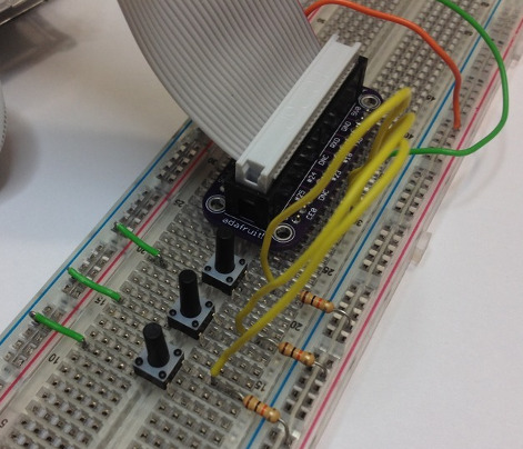
enter image description here

[Source: Adafruit]

  • The red wire is 3.3v power connected to the + rail on the breadboard; this corresponds to Vin from the diagram.
  • The green wire is ground, connected to the - rail on the breadboard.
  • The yellow wire is connected to a GPIO input pin, and corresponds to the logic gate and Vout in the diagram.

When the button is down/the switch is closed, voltage flows from Vin to ground, so the state of the pin, as determined by the logic gate at Vout, is 0/off. The reason for the resistor is to prevent a short circuit -- from the output which drives this circuit (red wire/Vin) and NOT the input (green/Vout) where you are testing the logic.

The term "pull-up resistor" can thus be misconstrued if we take it to mean a resistor which affects the input pin. It doesn't affect the input at all. The actual "pull-up" (a connection to Vin) is what affects it. The "pull-up resistor" is a safeguard on the pull-up.

The lesson here WRT to potential short circuits is don't accidentally set an input pin connected to ground as an output pin and drive it high.


1. Regarding that and something in your question: it is NOT 5V on the pi, it is 3.3V. There is a 5V output for powering 5V devices, but never connect that directly to any other GPIO pin or use it as the supply in a circuit such as we are discussing.

9
  • Adafruit shows two ways to interface a Pi with a magnetic switch. One uses a pull-up resistor and the other just uses the magnetic switch to connect to ground when closed. As you point out when the switch is open the input will be in a "floating" state, does this make using the pull-up resistor a better solution? Commented Mar 24, 2015 at 20:39
  • @HeatfanJohn If it's an arrangement that leaves the input floating, it seems to me it is not viable no matter what because you cannot tell the difference between that and "definitely off" or "definitely on". The floating state is not useful from an input perspective; it just represents the possibility of taking the pin out of action. If you have links for the adafruit stuff you are talking about I can look...
    – goldilocks
    Commented Mar 24, 2015 at 22:31
  • 2
    The input pin state is read at Vout, yes. When you use an internal pull-up resistor, Vin, Vout, and the resistor are all on the pin, but part of the point of my answer was when you have a pin set to input without an internal pull up, no resistor is needed between it and ground -- that is only the case for output pins which are set "on".
    – goldilocks
    Commented Mar 25, 2015 at 13:24
  • 1
    About those Adafruit links: The first one says WRT the door switch "with a 10k pull-up resistor to 3v3" -- so this is the same as the button pic. The second one says, "We will use the Pi's ability to create an internal pull-up resistor on the reed-switch pin, so we don't need an external pull-up resistor".
    – goldilocks
    Commented Mar 25, 2015 at 13:25
  • 1
    @GeertVc Yeah I get that -- I believe it's also a simplification to say the value of the input pin is tested at Vout, I think it is tested at the gate. But I did not want to take one confusing explanation and replace it with another overcomplicated one. Anyway, I've changed that to "corresponds to the logic gate and Vout in the diagram".
    – goldilocks
    Commented Mar 27, 2015 at 14:01

Your Answer

By clicking “Post Your Answer”, you agree to our terms of service and acknowledge you have read our privacy policy.

Not the answer you're looking for? Browse other questions tagged or ask your own question.