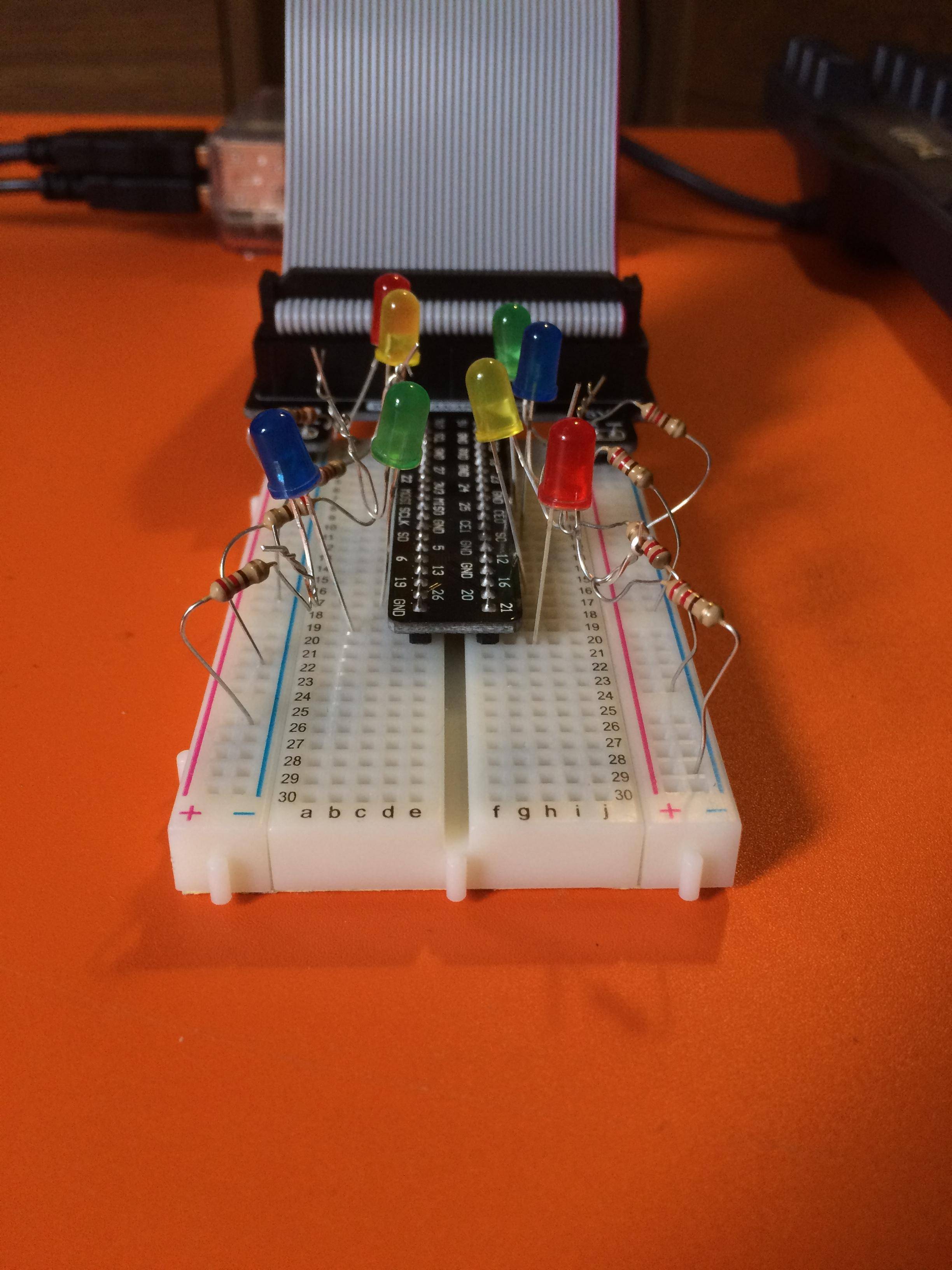
Currently I have my LED's anode connected to the GPIO pin that controls it and the cathode is attached to a resistor and the other end of the resistor is on my breadboards - rail. How can I use jumper cables so I don't have to twist and ruin all my resistors? All of the tutorials I find online show how to do it without a ribbon cable, which is what I am using.
Current Wiring: https://i.sstatic.net/EUFN7.jpg
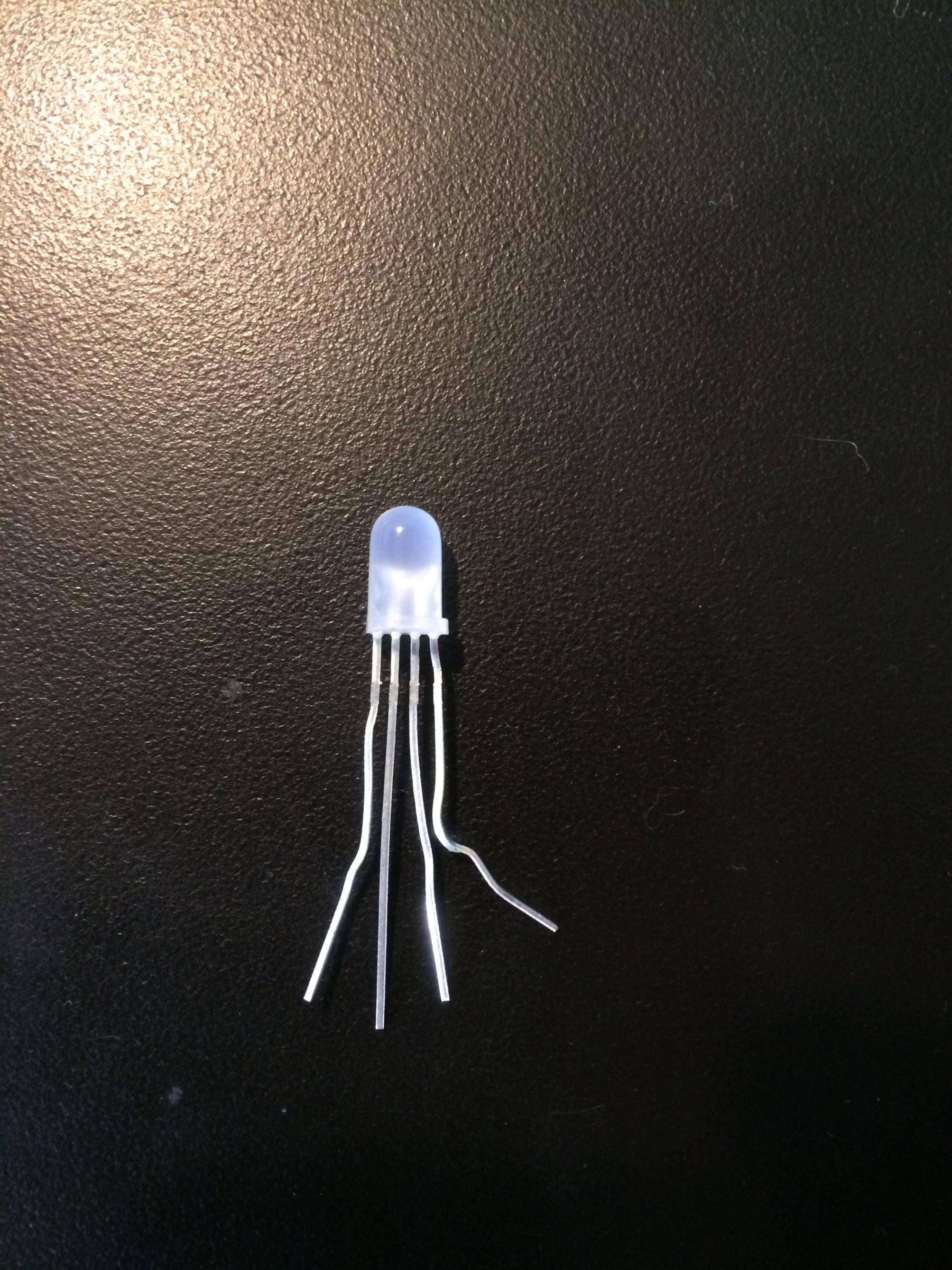
Also, a side question. One of the LEDs has 4 wires on it and it was not labelled what is what? How would I go about connecting that one up? I tried putting the longest of the 4 into the GPIO pin and then putting the smaller 3 connected to resistors onto the breadboards - side on the edge.
4 wire LED: https://i.sstatic.net/agxQk.jpg
EDIT: The white LED with 4 wires is this http://www.mpja.com/5mm-Red-Green-Blue-Full-Color-LED-4-Lead-Common-Anode/productinfo/17137%20OP/ and the longest wire is the anode and it now works fine. Now I need more than ever to figure out how to use the jumper cables so I have room to work with multiple GPIOs for this one light. Anyone know how to do that or could link to a guide?


