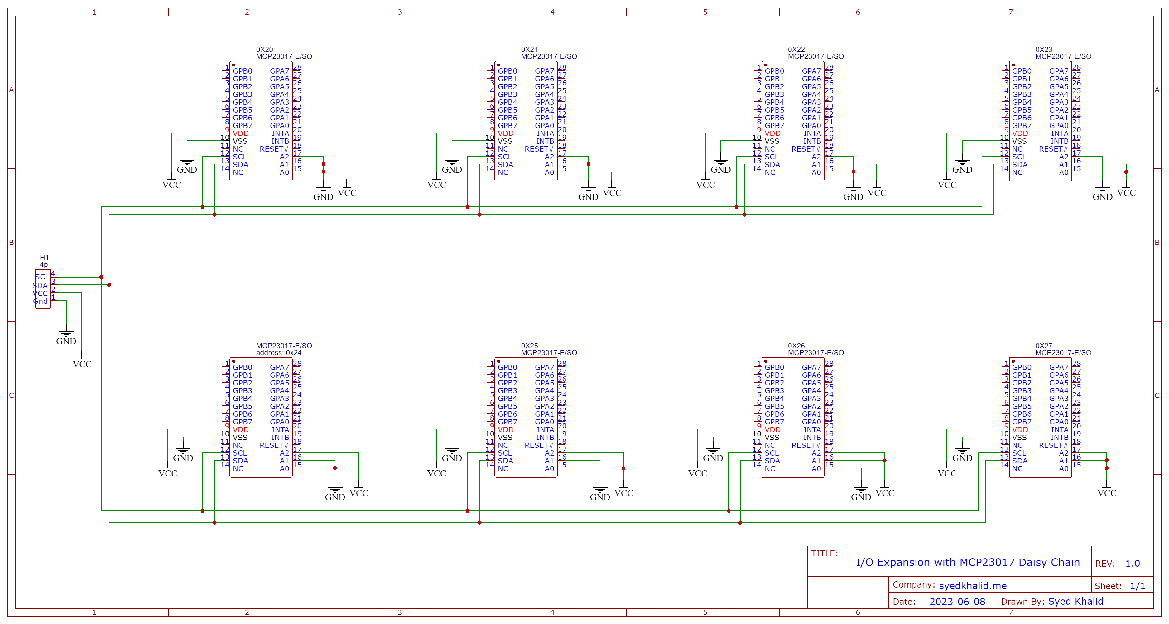
I've recently wanted to use I2C to communicate to multiple 23017s (PDF Datasheet) or Multiple 23008s (Smaller version of 23017). I saw this post, but it was never answered as to if the diagram was correct. I look at the attached diagram in the post and think it is incorrect and that the illustrator connected the chaining of chips to the outputs of the 23017s and not to the SCL and SDA lines.To rephrase, his diagram is using the GPB0 + GPB1 pins in order to daisy chain. Since the addressing is determined by the A0+A1+A2 pins, I think the daisy chaining should happen by linking pins 12 and 13 on the chips, am I correct?
Am I correct in saying that as long as I correctly ground the Address pins uniquely that I can wire straight from the Pi to all of the 23017's SCL and SDA lines (Like a big pig tail). In that sense there will not be an I2C link directly between the chips, but directly to the Pi. Or do I do the electrically equivalent and link the pins 12 and 13 of all the chips together and then chip 000 back to the Pi?
Then am I correct to say I can send the full message from the Pi to the chips, but the individual I2C chips will ignore the parts not addressed to them? If I have a message to chip 010 and I send it, it will reach every chip, but only 010 will respond because the other chips are not addressed as 010.
On a final note, there is a SPI variant of the 23017 (23S17), the diagram in the previously mentioned post looks to me like the SPI configured diagram discussed on this page here.
To restate, I'm looking for the correct way to link 23017 chips that communicate via I2C to the Pi.
Thank you for you time.

