2

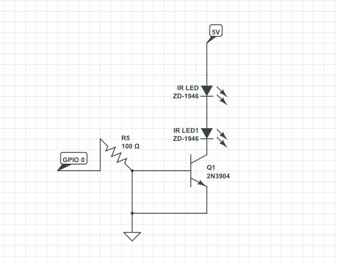
I've tried to imitate the below diagram for my Raspberry Pi using GPIO 0, without a receiver.

The diagram seems to show a resistor going to ground, and an (emitter?) going to ground as well. I know nothing about electronics (as you can tell), but I wired it together using this diagram. [this is one I made from the above one...] enter image description here enter image description here
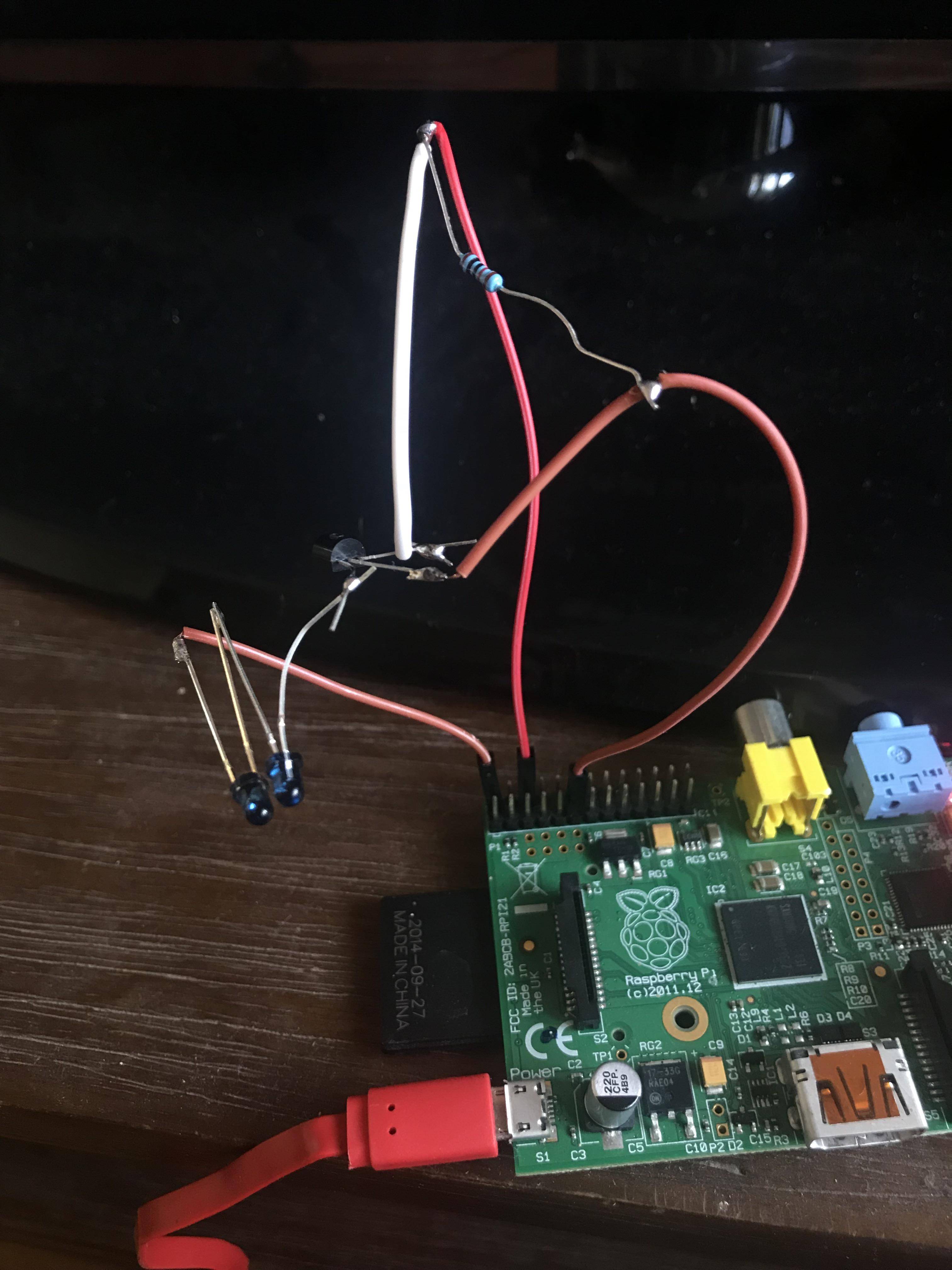
Using LIRC.

Is my wiring attempt ok?


EDIT: I ran a modified version, where I connected the base to the 10k resistor and then straight to GPIO 0, and the collector to ground, with the LEDs connected to 5v. The LEDs are now constantly lit.

SIDE-NOTE: Generally, I've been incredibly confused with the posts online with regards to the correct amps, voltage from the Pi — 3.3v, but don't know enough electronics to know if the LEDs will demand a certain current, or receive it regardless (which makes it hard for me to determine what the resistors are for).

The LEDs are 1.3v, 100mA, but the Pi is 3.3v and supposedly 60mA max per pin.

11

3 Answers 3

2

supposedly 60mA max per pin

No, this is one figure sometimes floated as a total maximum for all GPIO pins. Note the pure 3.3V/5V power pins are not considered GPIOs and can supply much more than this, perhaps 1 A in total. In the picture you are using a 5V pin, which should be fine.

I've routinely drawn 100-150 mA total without issues (but YMMV!). The limit per pin is usually (and I believe officially) given as 16 mA, but again from experience and observations by others here, 20-25 mA should be okay. In this case you are only using a GPIO to toggle the transistor, which can be done with a few mA or less.

Going back to your picture, the big 10k resistor is between the GPIO and ground, but there is no resistor between the GPIO and the transistor base. The one that's there is to provide a pull-down to ground, so that if the pin is set as an input it does not float, which would mean in theory it might trigger the base. This is probably not very necessary. What is more important is you have a resistor between the GPIO and the transistor -- so you can remove the ground connection there and just put the resistor inline with the connection to the transistor base pin.

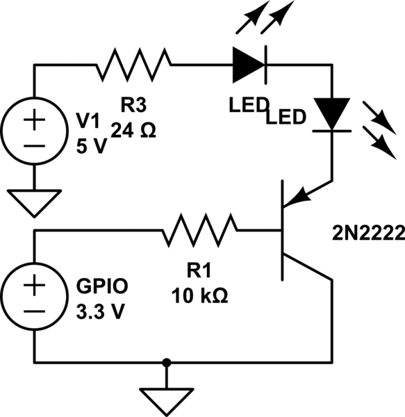
There should really also be a resistor somewhere between the power pin and the LEDs or the LEDs and the transistor. The LEDs have a forward voltage drop of 1.3V and there are two in series = 2.6V. So that resistor should be about:

(5 - 2.6) V / 0.1 A = 24 ohms

schematic

simulate this circuit – Schematic created using CircuitLab

Note the connection to ground from "GPIO 3.3V" does not mean you need to add that connection -- the pin is only the + aspect of the voltage source there, the other part is abstract.

6
  • Is 24 ohms negligible? Can I just omit that, as I don't have such a resistor?
    – yeeeeee
    Commented Jun 25, 2017 at 13:00
  • I'd just go with the smallest resistor you have. If not, LEDs actually do have some resistance, which should limit the current enough that at worst they will just burn out (possibly, not right away), i.e., the Pi should be okay. But that's not a promise from me (I'm no expert on electricity). Of course, it sounds like you've already tried it with no resistor and everything was well enough. Feel them in your fingers after a few minutes; if they are noticeably warm they are probably over-amped.
    – goldilocks
    Commented Jun 25, 2017 at 14:06
  • 10K is the smallest I have, other than 150. It's working, but even with two LEDS pointed apart, it has to be line of sight which is less than optimal. I don't know if their angles of coverage are wide enough, or they're just not bright enough. I was hoping to go from here to many more in parallel to switch multiple IR receivers in different rooms (over a long line, which is probably additional resistance…)
    – yeeeeee
    Commented Jun 25, 2017 at 14:18
  • If they aren't getting warm with no resistor then I think you are okay. You could get bigger and/or more LEDs and use them in a single cluster if you power them from something else, but still switch them with a transistor from the pi. E.g., using a 12V supply you could put 8 or 9 of those in series. I have a big universal remote hub here that will work via deflection (I can certainly block the line of site, dunno about separate rooms though) but I am pretty sure it has a lot more than 2 LEDs in it. It's saucer sized.
    – goldilocks
    Commented Jun 25, 2017 at 14:34
  • Two rooms, running a wire between the rooms. Need to design it, worried about resistance.
    – yeeeeee
    Commented Jun 25, 2017 at 14:38
2

A 2N2222 is an NPN transistor. What you have drawn is a PNP. If you are using a 2N2222, connect the emitter to ground and the collector to the cathode side of your LED.

0

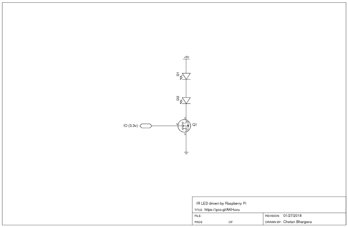
You have a better option to use a MOSFET

BJT in this case is less suitable because you are driving LEDs in Digital mode. LED brightness is of no concern; only on or off condition is needed.

@SRD is correct that the "Accepted" answer has the transistor in wrong orientation.

enter image description here

Your Answer

By clicking “Post Your Answer”, you agree to our terms of service and acknowledge you have read our privacy policy.

Not the answer you're looking for? Browse other questions tagged or ask your own question.