1

I found a 5 volt fan from an Acer laptop, and want to fit it to my Pi (sunon maglev fan GC055515VH-A).

It has three wires - red, black, and yellow - why is that?!

The unit does not state its amperage but, it draws 1.7 watts. Sounds like a lot but, will the Pi be happy powering it from the GPIO?

I'll have to split the wires out but, which pins do I attach to, and do I need to attach all three?

Oh, one more question! I think I've found out that the yellow wire is an 'output signal for rotational speed detection'. Could this be fun or, actually, useful?

Thanks, in advance.

1 Answer 1

1

Fan has 3 wires, red and black are for powering it up, yellow is for signal feedback to tell how fast is it going. It could be useful for setting constant speed of fan, but you don't have to connect it anywhere to run a fan.

Answering your question if the Pi will be happy...

TL;DR: No, it won't be happy at all

...because many things.

First, you can calculate how much current it takes, because power equals current times voltage, ie. P=I*V

You know the power, you know the voltage and you should know already that I = P/V so your fan draws 1.7/5 = 0.34A = 340mA

Now, maximum current per GPIO pin is 16mA, according to https://raspberrypi.stackexchange.com/a/9299/51759

So it's impossible to run because there isn't enough power available from pure GPIO.

Next thing is voltage. Your fan is rated 5V. GPIO outputs 3.3V. So even if you manage to get enough current from your pin, fan won't have enough voltage - should start (it's not guaranteed tho), but won't reach it's RPM.

But don't worry, it is possible to connect your fan. Just use NPN transistor like 2N3904, connecting it's base to your GPIO pin through 1Kohm resistor. It's well documented here: http://elinux.org/RPi_GPIO_Interface_Circuits#Using_an_NPN_transistor along with many alternative designs, so I highly recommend visiting this site.

I took a sample NPN circuit from there:
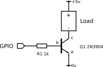
enter image description here

You just connect your fan instead of load and use one of the 5V pins (not the GPIO!). Keep in mind that your power supply should be capable of delivering enough energy to keep both Pi and your fan powered at the same time, so don't connect electric heater there ;)

3
  • This circuit is bad and only saved by the fact that 2n3904 is way beefier than the little fan motor. Inductive loads should have a flyback diode, or there is a chance to fry rpi one day switching the fan off when the transistor gets tired and decides to arc -100V. Your circuit also is limited to 100mA by the base 1k resistor
    – crasic
    Commented Aug 3, 2017 at 7:10
  • That being said your post is correct, and the transistor approach is good, you would not be able to run the fan of GPIO even for a second, its not a great idea to run inductive loads off the same power rail as digital electronics, but its doable if you are careful.
    – crasic
    Commented Aug 3, 2017 at 7:13
  • @crasic you're right, I uploaded the sample circuit from elinux.org for demonstration purposes. Maybe you could provide correct image so I can replace it? Or would you like to post another answer I can link to?
    – Mark
    Commented Aug 3, 2017 at 7:34

Your Answer

By clicking “Post Your Answer”, you agree to our terms of service and acknowledge you have read our privacy policy.

Not the answer you're looking for? Browse other questions tagged or ask your own question.