1

I am having trouble with a Pi 3B connected to a 16-channel relay board (something like this: https://www.amazon.com/Lysignal-Channel-Interface-Optocoupler-Protection/dp/B073GR9MPQ

The problem is this -- there seems a weird power interaction between the board and the Pi. The board has pins for the 16 inputs along with 5V and GND; it also has a separate 12V DC input which is required for the relays. I connect the pins to the GPIO of the Pi model 3B. I have to use 3.3V instead of 5V because otherwise the GPIO pins changing between lo and hi is not detected by the board. But this seems to work fine, and other people have suggested that it's ok to use 3.3V here.

Now, I noticed a strange thing, that is when I remove the Pi's standard 5V power supply, the unit is still somewhat powered, apparently through the relay board. The real problem however is that the Pi sometimes, and I don't know what triggers this, shuts down part of its peripherial controllers, namely the USB and the Ethernet (HDMI is not affected). At first I thought this was solved by powering the Pi first, followed by the 12V of the relay board. But now I had a situation where USB and Ethernet shut down after a random period running the system (around half an hour I think, I only noticed by coincidence).

I also have to say that I have stacked 9 Pis and 9 relay boards on top of each other, without using closing cases, so I think ventilation and temperature are ok. I am looking for any hints as to what is causing this -- is it harmful? can I recover without taking down the Pi and repowering it? Can I fix this somehow? Is there some message logs I should be looking at (can only do this after cold reboot, because I have no network and keyboard after the shut down).

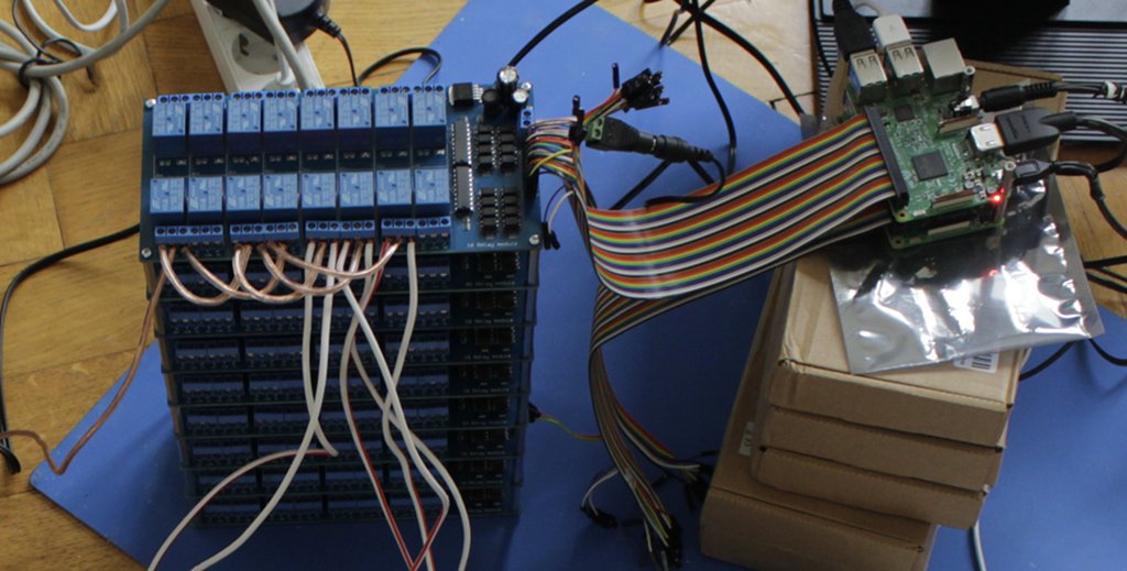
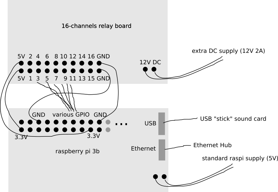
Below is a "schematic" and an older photo that has only two Pis set up so far.

enter image description here

enter image description here


Edit: I looked again at this video, and some comments go in similar direction. My theory now is that the board feeds 5V actively back into the GPIO's 3.3V supply. This is probably bad, but that was the only way I got the relays switching, and didn't notice any problems so far, it also seems to be what the guy in the video is doing. I'm in a very stressful situation, so any help getting this "fixed" with minimum effort would be appreciated (i.e. I have no time or resources to add regulator chips or whatever).

3 Answers 3

2

You will need level conversion (something like 4× 74AHCT125), and use the 5 V power instead of 3.3 V. Also, there's a good chance that the 16 optoisolators are drawing more current than a Raspberry Pi can supply, and that might be causing your USB controller (and hence Ethernet too) to shut down.

Backfeeding 5 V into the 3.3 V GPIOs could well damage your Raspberry Pi, especially when the 5 V is coming from a board with lots of inductive loads such as relays.

6
  • Thank you - do you think I can order a ready-made thing, like this amazon.com/… or this amazon.com/TXS0108E-Channel-Logic-Level-Converter/dp/B06XWVZHZJ - it's that I am in total stress for an exhibition and I have no resources to experiment with parts myself now. Would something like this work?
    – 0__
    Commented Aug 12, 2017 at 19:01
  • Instead I'd put 8 PI's aside and use 10 MCP23017 in a very easy layout using only 2 * i2c.
    – LotPings
    Commented Aug 12, 2017 at 19:33
  • @LotPings I understand I made a bad choice, but I need to fix a situation very quickly and with minimum knowledge and experiment, ideally by inserting something between the GPIO and the input pins of the relay board. Would something like this work: amazon.de/4-Kanal-Converter-Arduino-Raspberry-Mikrocontroller/… ?
    – 0__
    Commented Aug 12, 2017 at 19:36
  • 1
    I used these myself, they should do - but this requires 36 of them, new cabling and a lot of soldering.
    – LotPings
    Commented Aug 12, 2017 at 19:43
  • @LotPings thanks for the quick reply. I found an 8 channel variant now and ordered 18 pieces. I connected before with breadboard jump wires and no soldering, and so the only thing to solder is the little extra pins that come with the converter, and then I can insert the thing in between, so I hope I can solve the whole adventure in one afternoon :-O
    – 0__
    Commented Aug 12, 2017 at 20:34
0

Shut down of USB devices (as is the Ethernet port on the Pis) may also happen due to undervoltage of the 5V rail. What does vcgencmd get_throttled has to say? If your Pi has seen undervoltage since last boot, you'll see 0x50005, otherwise 0x50000, as far as I know.

3
  • Thanks - it reports 0x0, so I guess this is not a problem. The problem seems to be really, and I curse people for publishing videos showing how to connect the 5V driven board to the 3.3V GPIO, that the GPIO is now fed with 5V into its 3.3V supply; this "makes the relay board work", yes, but I suspect this is the source of the trouble, and so I need to know if this will permanently harm the Pi and if I can find any rather simple work around to perhaps protected the GPIO or whatever is sensing the higher voltage.
    – 0__
    Commented Aug 12, 2017 at 18:15
  • If you really feed 5V into the 3.3V them this will immediately kill the SoC, as the 3.3V is feed by a buck reg from the 5V rail, and the SoC is feed from the 3.3V rail. So you would immediately notice, as the SoC won't survive a 5V surge. See also: raspberrypise.tumblr.com/post/144555785379/…
    – TheDiveO
    Commented Aug 12, 2017 at 18:57
  • well, this is what my volt meter says, and several others working with these 16 channel 5V relay boards have said. I curse the people who put video tutorials connecting the Pi that way if it is actually harmful. Well, so far I had 9 Pis connected, none of them died in any way, but as I said, sometimes one shuts down. I can cold boot, and they seem all fine again.
    – 0__
    Commented Aug 12, 2017 at 19:10
0

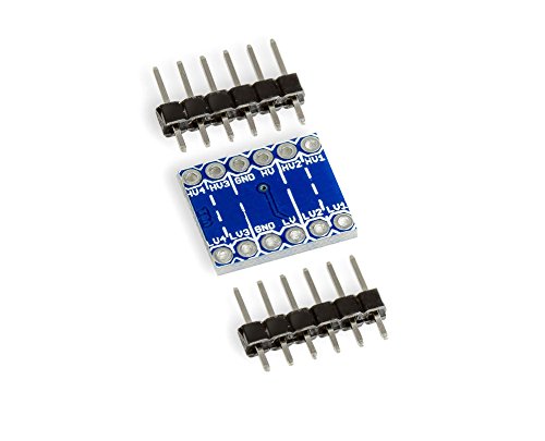
I can confirm that the problem disappeared after inserting those Logical Level Converters. I used two 8-channel converters, each with 3.3V, 5V, and GND attached to the GPIO, and the relayboard only having GND and the input pins attached, no need to connect its 5V "inputs" (which I think are reference outputs). The boards I used look similar to this:enter image description here

Your Answer

By clicking “Post Your Answer”, you agree to our terms of service and acknowledge you have read our privacy policy.

Not the answer you're looking for? Browse other questions tagged or ask your own question.