1

I have an appliance that needs a +12v pulse to be activated and a -12v pulse to be deactivated on the same input pin. After the pulse, the line should drop to 0v again. This voltage switching only has to happen once and a while. So at a very low frequency.

I think/know the outputs of a rpi can not produce negative voltage but I need a circuit that can put 0v, +12v or -12v on a line.

I guess I will need two output pins of a rpi to switch between 0v, +12v and -12v but I have no idea how to create the circuit.

Will I need to have two power-supplies to produce both +12v and -12v? Or are there IC's that only need +12v to do the job?

So if I have two input pins to the circuit (outputs from PI) i1 and i2 then the output o of the circuit should be:

i1 = 0 & i2 = 0 => o = 0
i1 = 1 & i2 = 0 => o = +12v
i1 = 0 & i2 = 1 => o = -12v
i1 = 1 & i2 = 1 => should not happen but should not damage circuit.

Thanks!

2 Answers 2

1

There are probably many ways of doing this, the most obvious one that comes up is using one 12V battery/power supply, and wiring its output to your appliance using some sort of relay switch modules. Ideally you would want to use a pair of 3-ways switches, which can be controlled digitally. I'm not sure what's avaialble on the market, but ideally that's what you'd want to use.

What i know for sure that's available and cheap and would work for you is simple on/off realy switch modules.

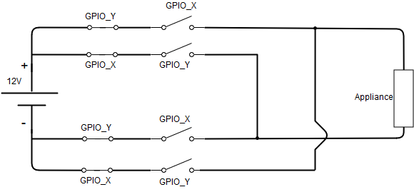
You would control the switching action of the normally open relays with the rpi GPIOs so that, if one pair of relays is switched, 12V is supplied to your appliance. And another pair of relays would connect -12V to the appliance. And you should probably also include some sort of protection from short ciruciting your power supply, maybe some normally closed relays, which open with the same signal as the normally open ones. Something like this picture would work.

enter image description here

You can see that i have included 8 switches, of which 4 are normally closed and 4 are normally opened. in this example all the switches are controlled by 2 GPIO from the RPI, without being specific let's calll them GPIO_X and GPIO_Y, as you could pick any 2 GPIO.

Assuming that all relays will act on and HIGH input signal:

  • If GPIO_X goes HIGH, and GPIO_Y is LOW, 12V is supplied to the appliance.

  • If GPIO_Y goes HIGH and GPIO_X is LOW, -12V is supplied to the appliance.

  • If GPIO_X and GPIO_Y are both HIGH or both LOW, the appliance is disconnected.

The reason why i'm including normally closed switches is to ensure that you can't short circuit the power supply by a mistake in your GPIO controlling software.

1
  • GPIO_X and GPIO_Y are basically your i1 and i2 as you called them in your question. Commented Oct 10, 2017 at 16:01
0

You may need to use a mosfet or relay to control the output. You will have to have one that uses the GPIO pins to trigger them which is 3.3v. You will also need a power supply to produce each of those output voltages you desire (12+ and 12-).

Your Answer

By clicking “Post Your Answer”, you agree to our terms of service and acknowledge you have read our privacy policy.

Not the answer you're looking for? Browse other questions tagged or ask your own question.