4

I love my little raspberry pi, and I am reviving an old home automation project, but instead of transmitting (in the old project, a butchered remote control) a signal at 433MHz (described here) to control plug sockets, I am trying to wire it up to the main lighting circuit in a room. I know that I could use that device, but it is quite bulky, and there is no way to accurately view the status of the device (i.e. rouge signals, other controllers, pressing the override button on the device itself).

To do this, I am going to open up the light switch, install a small 5v transformer to power the pi, then build a GPIO interface board that will control a set of relays that would be handling 240v, and a maximum of 13A (that is the fuse rating in the main fuse box).

Now, the interface between the GPIO pins and the Relay is causing me some issues. Can anyone provide any assistance, whether it be a circuit diagram or a module that I could reverse engineer, that can convert a 1-bit output from a GPIO pin to a relay capably of safely handling a mains supply?

I have done some searching so far, but the only components I can find so far that can be triggered by a GPIO pin can't handle 240v. I am also worried about any feedback or other circumstances that could cause damage to the GPIO controller (or worse, the entire device).

4
  • 1
    Use the GPIO to switch a transistor. That transistor will be connected to the relay, since the relay requires more current than the GPIO pins can handle. Also add a diode between the 2 pins in the relay (as flyback) to prevent damage to the pi. Just google around. There's tons of information about wiring a relay to a Raspberry or an Arduino. Above mentioned 2 things are the most important, to prevent damage.
    – Gerben
    Commented Jul 11, 2013 at 17:18
  • 1
    @Gerben that was my worry, but thanks. Would susa.net/wordpress/2012/06/raspberry-pi-relay-using-gpio be sufficient?
    – topherg
    Commented Jul 11, 2013 at 17:20
  • That circuit looks fine to me. That post looks pretty detailed. Good luck.
    – Gerben
    Commented Jul 11, 2013 at 19:18
  • I'll put what I build online. If I don't, assume that I went wrong... But I have found sainsmart.com/… which provides 4 relays that can handle 250v at 10A. It also appears to be a commercial implementation of the plans I have found, except it includes an optoisolator between the GPIO output and the relay triggering circuit, so, would the optoisolator be necessary or just overkill? It may be nice and cheap, but I still think I will build my own (as low profile as I can get) for the light controller
    – topherg
    Commented Jul 11, 2013 at 21:19

2 Answers 2

1

I wanted to achieve the same via Arduino. As Gerben said, a transistor to control relay and an optoisolator are the 2 parts that I reached at after a lot of search. Haven't experimented yet. As far as I have read, using an optoisolator is a MUST-TO-DO thing to keep your board and yourself safe and sound from high voltage mains.

1

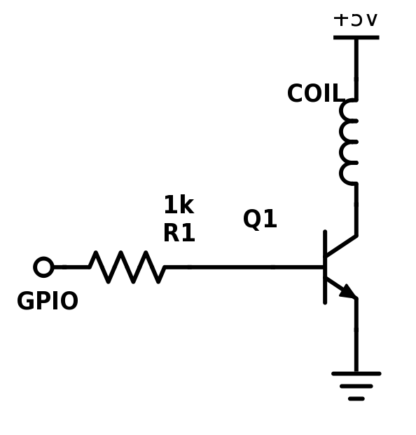
I suggest you use something like this.

BTW: The top cropped part is +5V

Your Answer

By clicking “Post Your Answer”, you agree to our terms of service and acknowledge you have read our privacy policy.

Not the answer you're looking for? Browse other questions tagged or ask your own question.