0

The usecase of my project is when I hear the sound of clap then only the relay channel should get triggered. But in my case, the GPIO.input(SOUND_INPUT_PIN) is only giving me value 1(HIGH). The connection seems correct, though. Below is the configuration of my pi, relay and small sound sensor.

pin 2(5v) -> vcc of relay

pin 6(gnd) -> gnd of relay

pin 7(gpio) -> IN1 of relay

pin 4(5v) -> vcc of sound sensor

pin 14(gnd) -> gnd of sound sensor

pin 11(gpio) -> DO of sound sensor

Here is my code

#!/usr/bin/python
import RPi.GPIO as GPIO
import time

# telling pi we are not using the pin but BCM standard GPIO names for the pins
GPIO.setmode(GPIO.BCM)

BULB_OUTPUT_PIN = 4
SOUND_INPUT_PIN = 17

# as I am refering to the BCM mode instead of BOARD mode so the output pin is
# GPIO4 which is 7th pin in the pi when starting the first pin from left.
GPIO.setup(BULB_OUTPUT_PIN, GPIO.OUT)
GPIO.output(BULB_OUTPUT_PIN, GPIO.HIGH)

# for sound sensor
GPIO.setup(SOUND_INPUT_PIN, GPIO.IN)

SleepTime = 6

# main loop

try:
    while 1:
        print('#######GPIO INPUT PIN##### ', GPIO.input(SOUND_INPUT_PIN))
        if GPIO.input(SOUND_INPUT_PIN) == GPIO.LOW:
            print("##########Sound is sensed############")
            time.sleep(SleepTime)
            GPIO.output(BULB_OUTPUT_PIN, GPIO.LOW)
            print("#Relay is triggered in the switch 1########")
            time.sleep(SleepTime)
            GPIO.cleanup()
            print("Good bye!")
# End program cleanly with keyboard
except KeyboardInterrupt:
    print("Quit")

    # Reset GPIO settings
    GPIO.cleanup()

UPDATE
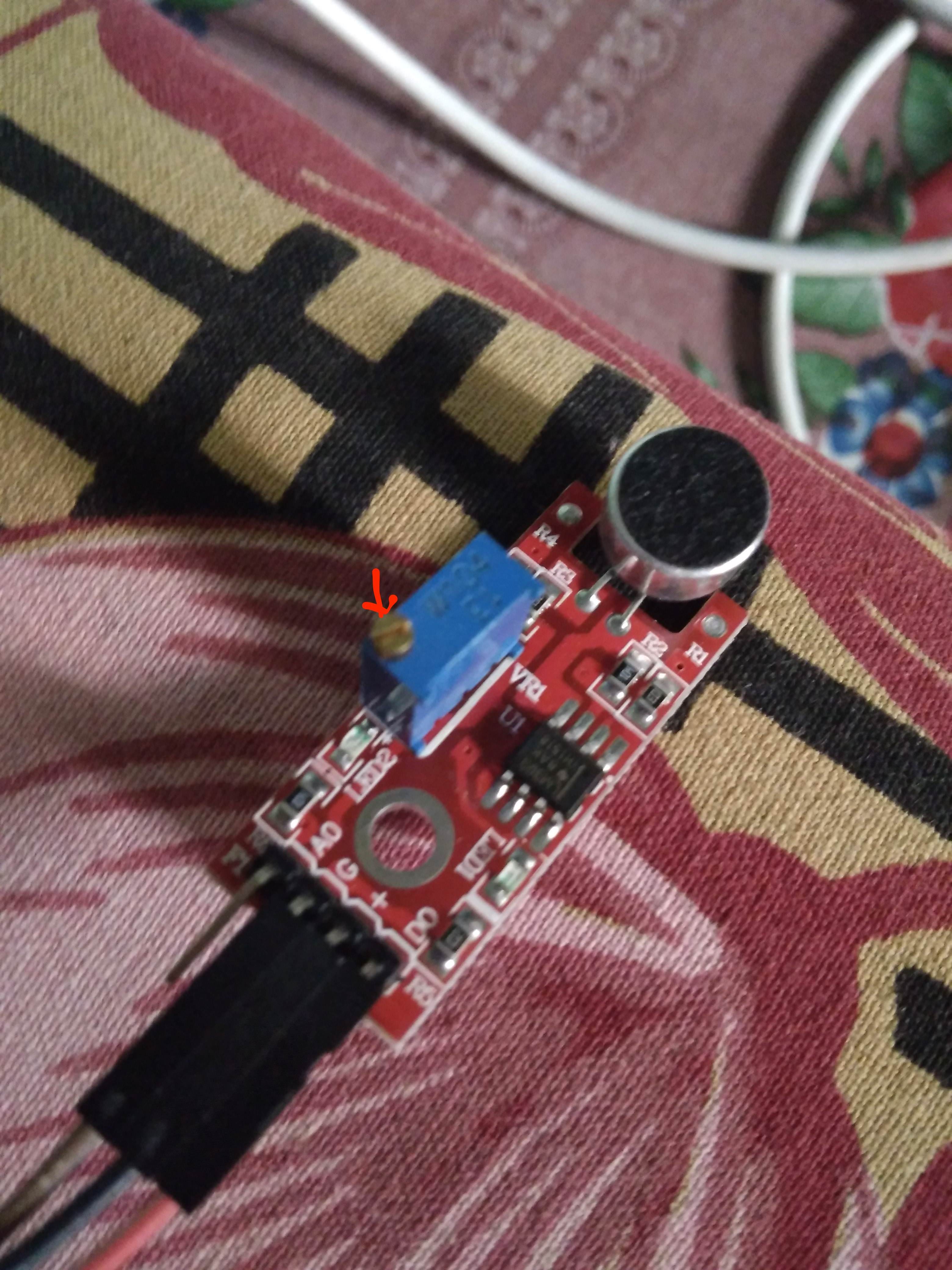
Sound Sensor.

1 Answer 1

1

You have given no details of the sound sensor you are using.

I assume it is a module with both an analogue and a digital output.

I assume you are using the digital output.

Sound modules with a digital output usually have a multi-turn potentiometer to set the threshold of the digital output. You will need to adjust the potentiometer to the level you want.

6
  • your assumptions are exactly correct but I apologize I did not understand your solution. Can you explain me a bit on "have a multi-turn potentiometer to set the threshold of the digital output", please?
    – milan
    Commented Aug 18, 2018 at 9:38
  • 1
    You need to use a screwdriver or similar to turn the potentiometer. Commonly they are a little blue box with a slot. You might need to turn it quite a few times. Some modules have an indicator LED showing when they are active. I'd initially try turning counter clockwise to lessen the sensitivity. These pots can have 15 or so full turns between high and low sensitivity. The number and direction of turn to lessen sensitivity will depend on the actual module you have.
    – joan
    Commented Aug 18, 2018 at 10:12
  • I have attached an image in my question where I have drawn the red pointer to show if that's the place to to turn the potentiometer? Sorry, just want to be totally clear so I don't mess up my sensor as they are very hard to get here in Nepal.
    – milan
    Commented Aug 18, 2018 at 11:28
  • @milan Yes, that is the pot and the arrow points to the screw to turn.
    – joan
    Commented Aug 18, 2018 at 11:50
  • yes that's really worked but sometimes i need to adjust it again and it works.
    – milan
    Commented Aug 18, 2018 at 12:32

Your Answer

By clicking “Post Your Answer”, you agree to our terms of service and acknowledge you have read our privacy policy.

Not the answer you're looking for? Browse other questions tagged or ask your own question.