3

I'm using a Pi Zero W and I'd like to connect a 5v source to a GPIO pin to detect if the 5v is on or off.

I know the GPIO is only digital I/O and 3.3v max, so is a simple voltage divider enough or do I need anything else? I've read this other topic and it mentions diodes and capacitors for safety?

My goal is detect if a TV is powered on by connecting the TV USB port (only +5v/GND wires) to the Pi Zero W. I've already verified with my multimeter that the USB port drops from 5v to 0v (slowly) once the TV is powered off. Ideally, I'd like 4.7v - 5v to be considered on and less than 4.7v to be off.

3 Answers 3

2

It's as simple as adding a simple resistor to limit the current flowing to the GPIO.
What we shall be carefull is to limit the current flowing "to" the GPIO, worst case when the input is 5V .

Three steps:

  1. define the GPIO pin as input.

  2. Add a pull_down. Thanks the BCM2836 design, each GPIO pin has an internal pull down resistor SW enabled. This pull down has a value in the range 40-100k. (Here electrical specifications of GPIO pins)
    This is the SW configuration of the GPIO as input with pull-down:

    GPIO.setmode(GPIO.BOARD) # Use physical pin numberin GPIO.setup(11, GPIO.IN, pull_up_down=GPIO.PUD_DOWN)

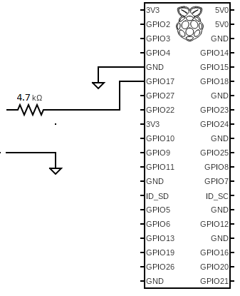
  3. add a series resistor of 4.7k that limits current to ~0.9mA, much less than the 16mA safely supported by each GPIO pin. With this resistor the switch from logical high to logical low will happen with when the input tension falls to ~2-3V (assuming internal pull down value 40-100k). In case you want the switch happens at an higher tension you should increase the value of the series resistor, but higher resistor means lower current and more sensitivity to noise. interface between pushbutton and Raspberry

Resistor in series to GPIO

0

It depends.

If you know the maximum possible voltage, say X. Then a voltage divider changing X to 3V3 will work and will be safe. This assumes that 5V is sufficiently close to X so that it will also be detected as high (so the voltage divider should turn 5V into something like at least 2.5V).

If you are ultra cautious use high value resistors in the divider and aim to limit the current to something like 250 microamps (a quarter of a milliamp).

If you are ultra ultra cautious also add a 3V3 zener diode into the mix.

2
  • Thanks! Is it possible to bias (?) the voltages so that ~5v - 4.5v will send 3.3v to RPi GPIO and less than 4.5v will send 0v? (i.e. once the TV USB drops to 4.5v, I want the RPi to see the GPIO as off).
    – SofaKng
    Commented May 29, 2019 at 14:27
  • Not easily for me (a software guy). I'd first choose a GPIO and then find what that particular GPIO detects as just on. I would then use a resistor pair which gives that voltage for a 4.5V input. An electronics guy might tell you to use a comparator chip. If I were you I'd probably use an ADC but compare against the regulated 3V3 line (i.e. use a voltage divider to drop to 3V3 then use a 3V3 ADC).
    – joan
    Commented May 29, 2019 at 15:19
0

It is possible (in principle) to detect 5V with a voltage divider, but connection to an external device introduces many additional issues.

The Pi GPIO typically changes state at ~1.2V - but no engineer would rely on using it to do more than determine ON/OFF. It is safe to assume <0.8V is off >2.0V is ON. See Voltage Levels

I normally design voltage dividers to produce 2.0V - this is safe and provides a reasonable noise margin.

This forum is not the appropriate place to detail EE issues.

I would strongly advise against doing this - it is unlikely to be reliable and risks damaging the Pi.

It is possible (and safe) if the circuitry is isolated - I suggest using an opto-isolator.

Your Answer

By clicking “Post Your Answer”, you agree to our terms of service and acknowledge you have read our privacy policy.

Not the answer you're looking for? Browse other questions tagged or ask your own question.