3

I have a zero W powered via USB from a laptop. I have setup up for the SPI drivers and run a very simple test program which is:

import spidev  
import time  
spi = spidev.SpiDev()  
spi.open(0, 0)  
spi.max_speed_hz = 500000  
spi.mode = 0  
try:  
    while True:  
        resp = spi.xfer2([0xAA])  
        time.sleep(0.1)  
except KeyboardInterrupt:  
    spi.close()  

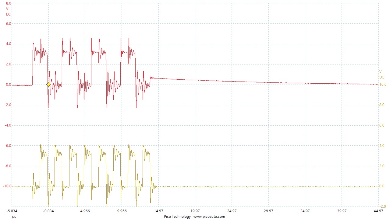
I get the correct output but the waveforms are so noisy. Figure 1

SCLK and CE0
The yellow is the SCLK pin, the red is the CE0 pin

In figure 2:
SCLK and MOSI

The yellow is the SCLK pin and the red is the MOSI outputting one byte of 0xAA
The voltages are between 0 and 3.3. I looked at this because I can not receive data by the slave, but there could be a hundred reasons for that. What I would like to know, is this noise level normal and could it affect the slave device.
Many thanks.

4
  • Probably not the best place for this question. We have no idea of how you are visualising the waveforms, what kit you are using, how you have attached the probes etc.
    – joan
    Commented Sep 13, 2019 at 13:22
  • @Jon Anthony, Ah let me see. I used to test SPI setup by running a loop back program. You might like to read my test program which loops back successfully and the wave form displayed. I also used a repeat send byte program to watch how the noise looks like. raspberrypi.stackexchange.com/questions/100237/…
    – tlfong01
    Commented Sep 13, 2019 at 13:34
  • I am testing Rpi's 5 SPI channels, 0.0, 0.1, 1.0, 1,1, 1.2. I was casual in the tests, using long connecting wires > 60cm, and scope ground lousy. I have another test more serious. Let me see if I can find it. I am doing SPI for my MCP23S17s and results is more or less OK. Using I2C to play with MCP23017, on the other hand, was a big mess, ...
    – tlfong01
    Commented Sep 13, 2019 at 13:43
  • My answer to the first question below has a better screen capture of the SPI waveforms (Scroll down to Fig 11 of my answer). You still see switching spikes but they are not noise). (1) raspberrypi.stackexchange.com/questions/98549/… (2) raspberrypi.stackexchange.com/questions/99353/separate-spi-data (3) raspberrypi.stackexchange.com/questions/99079/…
    – tlfong01
    Commented Sep 13, 2019 at 13:49

1 Answer 1

3

These look like signals which have travelled along quite long wires with no termination, which were packed together. Using shorter wires and running SPI signals in a flat cable with GND lines in between signal lines will help. Adding a 30 Ohm series resistor on the CLK line (near the master pin which drives it) could be the next step.

Even then, your signals look acceptable and I wouldn't spend time on getting them super-clean as long as everything works, unless your ultimate plan is to run SPI at a much higher frequency. Your slave not receiving the data is almost certainly due to something else: noise would rather make it receive incorrect data.

4
  • Hi @Dmitry Grigoryev, I agree with you on the wire length, no termination etc (Actually I never bother to care about termination. I always they were for range VHF/UHF transmission) . And what the OP says noise are actually RINGING, which are reflections (not sure, forgot all that). For my Micky Mouse projects, I always use SPI frequency as low as 100kHz, and sometimes even down to 10kHz! So I never worry about noises. I also always use 3V/5V level converters/buffers (5V can tolerate higher noise than 3V3) such as HCT125 (check out AdaFruit) which help driving long wires, ...
    – tlfong01
    Commented Sep 13, 2019 at 13:58
  • And you might like to look at the picture of "noise" in my logical level converters experiments, in my answer to the question below: raspberrypi.stackexchange.com/questions/27928/…. In other words what the OP worries are "ringing", not "noise", and can be completely removed (only 50% sure!).
    – tlfong01
    Commented Sep 13, 2019 at 14:07
  • Hi @Dmitry Grigoryev, the wire length from the RPi to the scope lead is 3 inches. The PicoScope lead was about 18 inches. I assumed the scope would provide termination. I will try to see if shorter leads give a better picture. Why I could not connect was due to polarity and phase issues. Many thanks. Commented Sep 15, 2019 at 9:24
  • @JonAnthony The scope never provides termination since termination alters the signal and the very purpose of a scope is to display unmodified signals. What you should try is switching your probes to 10x if you haven't already, and tune the probe compensation in a way that the test signal on AWG port of the scope looks perfectly rectangular. Indeed 3 inches is not long, I'm actually surprised that you connected two devices with leads that short. Commented Sep 15, 2019 at 10:02

Your Answer

By clicking “Post Your Answer”, you agree to our terms of service and acknowledge you have read our privacy policy.

Not the answer you're looking for? Browse other questions tagged or ask your own question.