0

schematic

simulate this circuit – Schematic created using CircuitLab

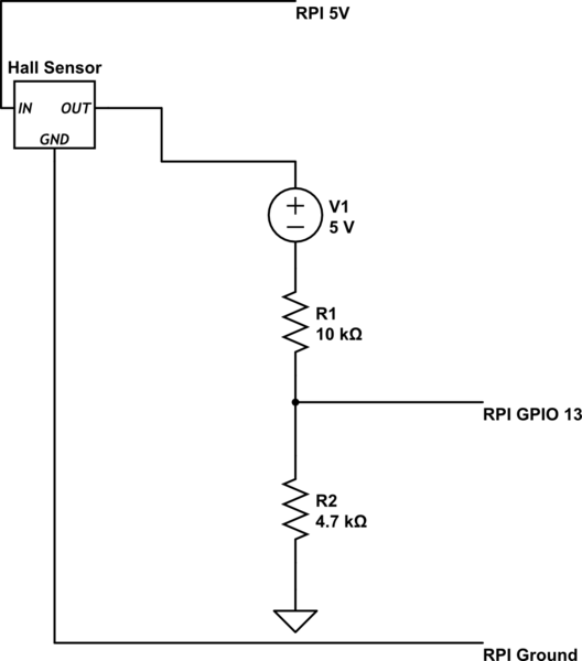
I have a very simple circuit that uses a hall effect sensor to measure water flow which then in turn sends pulses to GPIO 13 on my PI. Problem is, for some reason the count of pulses is way below what I know the rate of speed of the impeller to be. Has anyone seen this issue? I have a simple setup of the ground direct to the board, the 5 V direct and pulse output through a voltage divider back to the PI. Its odd that I get a good reading, and a pretty consistent on the number of pulses, but its like 5 a minute.... yet the sensor has 4000GPH going through it.... Could my voltage divider be causing this? I am using a 10k and a 4.7k. Any other issues that anyone can think of before I assume a faulty magnet in the housing?

4
  • 2
    Can't see any Pi relevance. You need to add wiring schematics. A voltage divider sounds odd on what should be an open collector output.
    – joan
    Commented May 5, 2021 at 16:07
  • pfobably not connected correctly ... replace the sensor with a pushbutton switch and press it a bunch of times
    – jsotola
    Commented May 6, 2021 at 1:45
  • We need to see a circuit diagram as your description does not make sense. Don't you mean "I have a very simple circuit that uses a hall effect sensor to send pulses to GPIO 13"?
    – justinjt
    Commented May 6, 2021 at 21:58
  • Edited to help clarify.
    – bbensten
    Commented May 7, 2021 at 12:31

1 Answer 1

1

I'm going to guess what your circuit really looks like because the schematic does not look reasonable to me.

I'm guessing that you have used two resistors as a voltage divider to reduce the maximum voltage from the sensor (around 5V) to something that is compatible with the 3V inputs of the RPi. The resistor values look appropriate, but you have reversed their locations. The 10 kilohm resistor should be between the RPi input and ground, while the 4.7 kilohm resistor should be between the RPi input and the sensor output. I don't think you really have a voltage source V1.

You can calculate the RPi input voltage as

V_{PI} = V_{SENSOR} * R2/(R1+R2)

Your Answer

By clicking “Post Your Answer”, you agree to our terms of service and acknowledge you have read our privacy policy.

Not the answer you're looking for? Browse other questions tagged or ask your own question.