0

schematic

simulate this circuit – Schematic created using CircuitLab

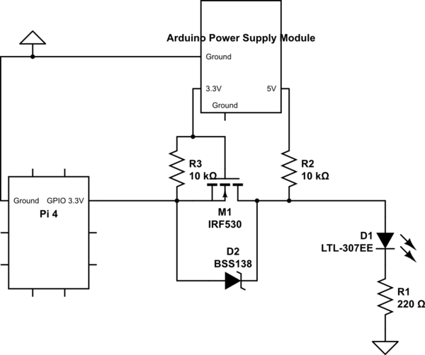
I am trying to use an Arduino Power Supply Module to provide enough power to allow at least 5V and 10 mA through to an external supply. I was wondering if, using level converters/shifters, if I could connect my Pi to the module. I was having some trouble. It is my understanding that if I connect the Pi ground to any ground on the module I should be fine. The idea was that the module supplies 3.3V+G on one side of a level converter, and 5V+G on the other side, while the Pi supplies the input pins. I wanted a simple circuit that would just have a GPIO pin supply output from the Pi to a low voltage side, then the high voltage side will go to an LED, then resistor to ground.

An equivalent version of the module: https://m.media-amazon.com/images/I/71ecltR6HdL.\_AC_SL1300_.jpg

The level converter: https://aws1.discourse-cdn.com/arduino/original/4X/4/b/6/4b6b7d6497b4ebd673cfdf9286ab01169a32e241.jpeg

The circuit has the Pi, the Arduino Power Supply Module, and a simple design of what I wanted to build. The idea was that the Arduino Power Supply module powers both sides of a level converter. The level converter is simply a transistor and some resistors that will output voltage on 1 side if there is voltage on the other side. In this case, 3.3V from Pi allows the 5V from the power supply to go to the LED.

The Arduino Power Supply Module just allows you to have 3.3V and 5V outputs, up to (from what I could find) 700 mA based on the power supply used to power it, rather than the normal 50 mA you would get from a Pi's 3.3V line.

7
  • 3
    No one can tell from a picture what these devices may do. Neither does your Question clarify what you are ACTUALLY trying to do.
    – Milliways
    Commented Oct 18, 2021 at 6:26
  • 2
    Your question is unclear. Please add a schematic to clarify your question.
    – Seamus
    Commented Oct 18, 2021 at 6:48
  • 1
    Added a schematic to give an idea of what I wanted to build. Commented Oct 18, 2021 at 7:09
  • @Eamon Brennan, your question is interesting, though a bit complicated, because a couple of things are intermingled together. My usual trick is this: Eat the big elephant bite by bite, in your case, by three bytes. The "system" consists of three "sub systems": (1) A dual, 3V and 5V power supply, which can be used for Arduino, but also for anything that requires 3V, or 5V, or 3V and 5V at the same time. (2) Rpi4B, to control the switch, which is this: (3) A power MOSFET switch. This switch can be used to control, for the time being, a "load", which is a simple LED status indicator.
    – tlfong01
    Commented Oct 18, 2021 at 7:31
  • 1
    The circuit you have now included in your question (which misuses a level converter) will do NOTHING apart from (dimly) lighting a LED. It uses neither the Pi nor Arduino.
    – Milliways
    Commented Oct 18, 2021 at 8:38

2 Answers 2

1

The circuit you have chosen represents a bidirectional level shifter: each side (3.3V and 5V) can simultaneously drive the line. This is sometimes necessary, e.g. with the I2C communication standard where both SDA and SCL lines are driven by the master and the slave at the same time, or with the half-duplex UART which uses a single bidirectional line for both RX and TX.

However, the ability to pass signals both ways comes at a price, specifically, this level shifter's current gain is less than 1. If your LED needs 20 mA, you'll need to provide more than 20 mA through the Pi GPIO, which will not be possible. Note how R2 in your circuit is useless: when the LED is lit, it's effectively in series with R1, limiting the current though the LED to < 0.5 mA. You'll get more current through the LED if you connect it to the GPIO directly.

If your goal is to drive a powerful LED, use a common emitter / common source amplifier which is able to boost both voltage and current. If you need to drive a digital circuit (like Arduino pins), you'll still be better off with unidirectional level shifters, which work at tens of MHz with common components. Your bidirectional schematic will not be able to switch faster than a couple hundreds kHz.

3
  • Thanks. I'm most likely going to build a similar circuit to this but use a different set of resistors. This current circuit was pre-built to allow up to 4 different inputs. If I build my own, it most likely only needs to be one way, and allow up to 10 mA at 5 V. Actually, quick follow up question: Could I get 10 mA out of this level converter? That's all I need for my project. Commented Oct 18, 2021 at 18:04
  • This level shifter would be quite inefficient at any significant currents, because the current you need has to always flow: either into the LED when it's on, or into the MOSFET when the LED is off. Compare this with a common emitter amplifier, where the current only flows when the LED is on. If you have just one LED like that, wasting 10 mA is not so bad, but try to drive a LED strip with 100 LEDs and you'll suddenly realize your project needs a heatsink and a fan. Commented Oct 18, 2021 at 19:54
  • It's to run a solid state relay, which only needs 10-15 mA at >3.5V in order to turn on. That relay will turn on the external voltage for other electrical needs. I think the level shifter will be fine with the info you have given me. Commented Oct 19, 2021 at 1:53
1
  1. The module "Arduino Power Supply Module" is just a Module that contains two "voltage regulators", so its a Dual voltage regulator module.

  2. If you are going to connect electrical devices they need a common ground.

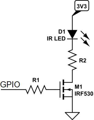
  3. If you want to drive LEDs from a Raspberry Pi, then you can do it in a much simpler way with just a transistor or directly. Check what capacity a Raspberry Pi 4B can drive from the GPIO. And since a LED don't need higher volt than 3 volt there is NO need for 5 volt.

Check out this link https://www.youtube.com/watch?v=CD9-oPzJL0I about transistors (MOSFET is a transistor).

enter image description here

5
  • The main idea was, I needed to supply at least 3.5V at 10 mA to a solid state relay to get it to run. The Pi cannot give this much power, as the GPIO maxes out at 16 mA at 3.3V, but also caps out at 50 mA on the entire 3.3V line, so I would only have access to 2 or 3 GPIO pins max. The LED is more of a test. Commented Oct 18, 2021 at 17:39
  • @EamonBrennan You can still use this schematic with 5V, no problem. At 10 mA of current you don't even need R1, you can connect the GPIO to the MOSFET directly. And you will certainly need a different MOSFET: IRF530 is an 80W beast which itself needs about 8-10V to switch on properly. It won't work reliably with 3.3V at the gate. Commented Oct 18, 2021 at 20:02
  • @EamonBrennan Use a ex. IRLM2502 instead of the IRF530.
    – MatsK
    Commented Oct 19, 2021 at 4:09
  • @DmitryGrigoryev R1 has a function, to protect the Raspberry Pi's output.
    – MatsK
    Commented Oct 19, 2021 at 4:11
  • The IRF530 with diode was already created as one piece, along with the 10k resistors. I planned on using them directly with the Pi's GPIO to convert to 5V, but now I'm going to put the Pi through a 2N2222 to get 3.3V at 10-15 mA, then convert that to 5V using the level converter. It's probably easier to use the 2N2222 directly, but it's a school project and I wanted to use as many parts as possible for a higher grade. Commented Oct 23, 2021 at 2:40

Your Answer

By clicking “Post Your Answer”, you agree to our terms of service and acknowledge you have read our privacy policy.

Not the answer you're looking for? Browse other questions tagged or ask your own question.