2

Edited:

Question re-written

Hello,

So I am looking to build a system that will have around 400-500 input buttons. These buttons are basically used to select an option so only 1 button will ever be activated at any given time.

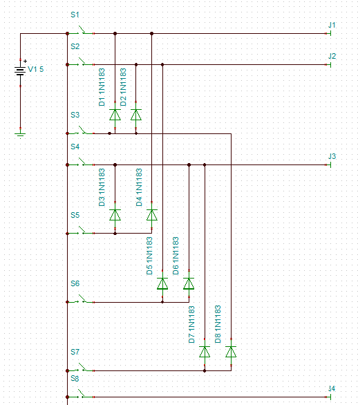
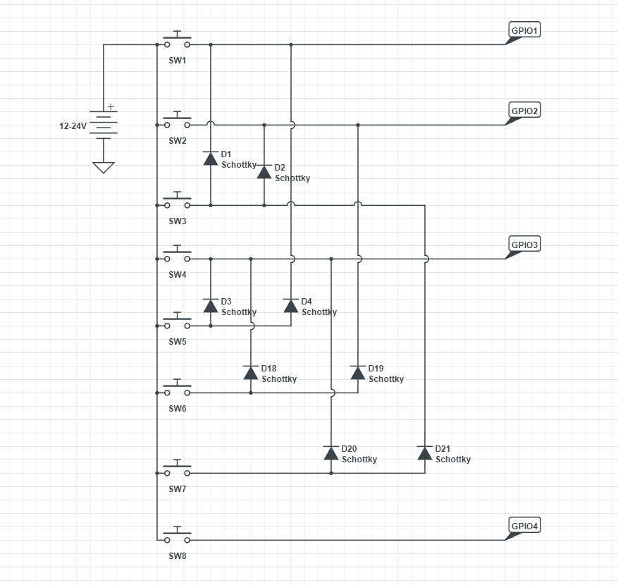
Below is a rough mock-up of a circuit I have designed that will allow the buttons to work like a binary input to the pi's GPIO pins.

By this I mean;

If you press button 3 below GPIO 1 & GPIO 2 will be activated. So when I read in the 4 GPIO pin states in the Pi I would see: 0011 which when converted to decimal will give 3.

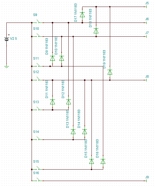
The circuit allows for 8 inputs, but I have worked out that if I repeat the circuit 7 times and then link them into a further circuit I can build a chain of these to give a total of 512 buttons using 10 GPIO pins. I have made an excel file to simulate the connections and check it calculates out correctly. I would upload this but it's on my work pc.

Where I am looking for advice/help is;

  1. The cable length from the Pi to these buttons could easily hit 3m. Would I be able to run these using the Pi's 3.3v or would the length become an issue?

  2. Protection - I've never had to fully design protection so advice on where to place resistors & values would be greatly appreciated.

  3. if the 3.3v from the Pi is not my best option, what would be your recommendations for isolating the pi from a larger supply voltage. In the past I have done work with using a Picaxe chip to drive some darlington pair transistors to run some point motors for a model railway. Would this be a good route to go, or would something like optocouplers be a smarter choice?

Hopefully this is better written than my original & I apologise for the poorly written original & delayed rewrite. Work this week has been a killer so my mind wasn't in the best state.

Circuit Diagram

Edit:

Further details on what I mean by combining to get up to 512 buttons. I would use break out boards like this;

Board 1 (first 8 buttons); Board 1

Boards 2 to 7 (giving up to 64 buttons). The J numbers would continue counting on each subsequent board;

Board 2

All of the above 8 boards would then feed into this board (linked on the J numbers); Joiner Board
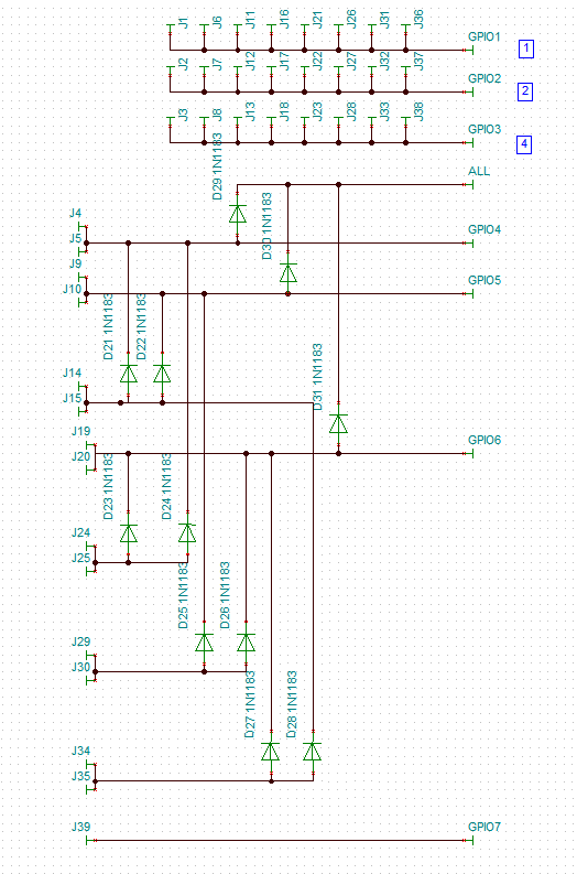
The All pin would then be used if more inputs are needed and further joiner boards are added to the chain (in the same way J5 is used). To add further in the chain you would use the joiner board but add another 3 rows (same as those being used for GPIO1 to 3) for GPIO 4 to 6. The diode structure would then start on GPIO 7. The GPIO 7 on the first joiner board would become a jumper the same as J9

8
  • 1
    This is too vague BUT if you connect anything >3.3V to GPIO you will have a dead Pi.
    – Milliways
    Commented Mar 16, 2022 at 10:52
  • 1
    Best bet is eight MCP23017 I2C chips and eight MCP23S17 SPI chips. They give you 16 gpios per chip. So that combo of eight of each gives you 256 GPIOs. Then wire switches to 12V/24V opto-couplers wire the opto-couplers to the 5V MCP23x17 chips.
    – Dougie
    Commented Mar 16, 2022 at 12:19
  • Thank you for the replies. I will try to update it better when I get home
    – opalbow
    Commented Mar 16, 2022 at 17:03
  • Hopefully the revised question is a bit clearer
    – opalbow
    Commented Mar 18, 2022 at 13:52
  • What you have drawn would work and you could extrapolate to 511 inputs using > 2200 diodes (no point in Shottky) but it is still an EE question - not Pi specific. (This was used with relay logic in the 1960s.) If you connect anything >3.3V to GPIO you will have a dead Pi. If you want to pursue this approach you would be better to use PLA, but most engineers would use a matrix and a microcontroller (such as Pico or Arduino).
    – Milliways
    Commented Mar 18, 2022 at 22:54

2 Answers 2

0

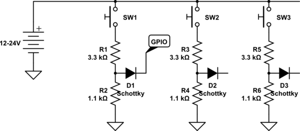
This isn't an answer; it's more of a guess as to the question you are trying to ask. You can copy the schematic below into your question & modify it using the schematic editor to better reflect your idea/question.

I am guessing that you want something along the lines of a button-press that creates a logic HIGH input to a GPIO, and a wired-OR to connect 2 GPIO inputs (that from your mention of a diode)???

schematic

simulate this circuit – Schematic created using CircuitLab

2
  • Thank you for your comment. I have updated my question now to clarify what I am trying to do
    – opalbow
    Commented Mar 18, 2022 at 22:35
  • @opalbow: Glad it helped - I'll delete it shortly as it's not a proper answer. Good luck with your project. And FWIW, the point of your Q being "off-topic" is one that comes up frequently here. The "on-topic" area covered by RPi SE has a very fuzzy boundary; we are in an area covered by at least 3 other SE: Unix&Linux, StackOverflow and Electrical Engineering. Hope that helps.
    – Seamus
    Commented Mar 19, 2022 at 0:59
0

Have you considered what happens when (not if) someone pushes two or more buttons simultaneously?

I think a row/column matrix would be easier with each button connecting one row and one column. The Pi would assert the row lines in turn then scan to see if any of the column lines are active. Because at any given time only one row/column pair is being checked multiple button-presses might not be an issue. With a hardware latch you could use your GPIO pins to write to the rows then use the same pins to read the columns.

It's usually easier to fix software bugs than hardware ones.

1
  • Hi, I know it seems like a when someone presses more than one, but for my use it isn't. Each will be linked to play a video on a screen and only a single user. It's a present for my partner so I know only 1 button will ever be pressed
    – opalbow
    Commented Mar 22, 2022 at 8:21

Your Answer

By clicking “Post Your Answer”, you agree to our terms of service and acknowledge you have read our privacy policy.

Not the answer you're looking for? Browse other questions tagged or ask your own question.