0

I'm building this mostly finished hydroponics system. It's a surge tank build.

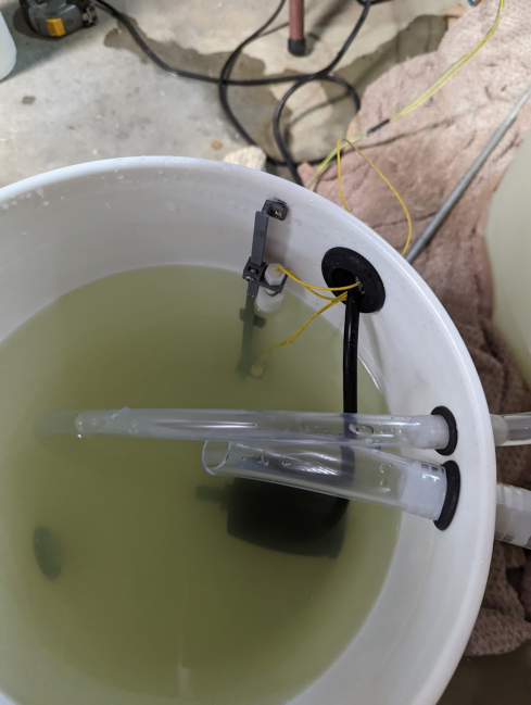
Surge tank looks like:

Surge tank with sensors

(that's nutrient water, it's got electrolytes that plants crave)

Inside that bucket are two simple reed float switches (these to be exact) to detect water level. They're open when the float is up and closed when the float is down.

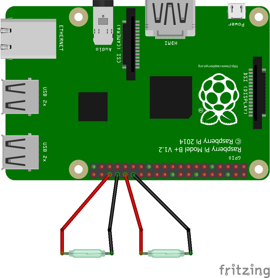
The total pi diagram: pi connections

I'm using raspberry pi's internal pull-up resistors on those gpio pins that go from the pi to the switch to gnd. I think they're like 50k ohm? That's what people online say, the datasheet is does not specify. Pi gpios are 3.3V rated.

So the pullup resistor basically connects internally such that when the switch breaks the circuit (open), the internal resistor is overcome and the pin reads as 1. When circuit is closed, current flows through the switch into gnd, so the pin will read 0 to the pi.

Problem

The submerged (bottom) switch gpio keeps frying no matter what gpio I use after a few days. (confirmed to fail tests with pigpio ./gpiotest, all pins were passing tests before the project). This is the second pin fried in a week and it seems to happen after a few days of stable usage. The top one has been fine for 2 weeks and counting. The only thing I can think of is the bottom switch is submerged and therefore open more often which would mean the current is flowing internal in the pi a lot? Meanwhile the top sensor is closed to gnd more often? Could leaving an open gpio in pullup mode for a while really just fry it? Is the wire picking up stray signals? Electrostatic? I have no clue why these pins are frying. Would a short with the water even do anything?

3 Answers 3

2

This is not really a Pi question.

You are ignoring most of the environment - what else is connected; I assume the solution is connected to some kind of pump and is conductive - this is almost certainly causing spurious voltages and your Pi GPIO are TOTALLY UNPROTECTED.

If you want to do something like this in a hostile environment it should be totally waterproof.

The other issue is that you have connected long antennae to your GPIO (you don't say how long the wires are) so they will pickup any EM interference going. Internal pullups are OK for short connections adjacent to the Pi. Use low impedance pullup like 470Ω.

The current flow 66µA is negligible - probably not enough to "wet" the contacts (unless they are gold plated) and would not be a problem.

PS I am sure the typical 50KΩ is specified, but in any event is simple to measure - just connect a 50kΩ to the GPIO and measure voltage then calculate.

NOTE If I was going to do something like this I would ensure it was galvanically isolated e.g. with an opto isolator but this requires some other source of power.

3
  • Forgive my novice grasp on circuits, I thought the internal resistors would be enough protection. Could you elaborate as to why a lesser impedance results in higher protection? Is it worth it putting a capacitor on the gpio for protection as well?
    – Slight
    Commented May 20, 2022 at 5:01
  • 1
    @Slight This is not the place for a course in Electrical Engineering, but the lower the impedance the lower the voltage that results. A capacitor will limit rapid rise time and thus HF but unlikely to help much although it won't hurt debounce processing is more effective. Interference limitation is somewhat of an art even for EE and each case needs to be considered on its merits. Low impedance circuitry is the cheapest and invariably the most effective.
    – Milliways
    Commented May 20, 2022 at 6:09
  • Thanks, that's helpful. I think that information is useful as it only takes a sentence or two to explain the reason the solution works and Raspberry pi still overlaps with electrical engineering topics, the main usage of a pi is to control electronic systems after all.
    – Slight
    Commented May 21, 2022 at 1:21
2

You likely have another power supply in your system (for the pumps, etc.) and it's likely much higher voltage than 3.3V. You need to make sure there's no way for the current to go from this power supply into the Pi GPIO, which is a non-trivial task in a wet environment.

If you have a multi-meter, switch everything off (keep the water in the bucket) and measure the resistance between the Pi GPIO that you use and the places where the high voltage could go, like positive supply wires or pump terminals. Ideally it should be > 1MOhm between any two points. If this is not the case, you need to make your wiring more water-proof.

1
  • The issue was likely that the pump inside the water, close to the bottom sensor, was sending strong enough EM pulses through gap to the open circuit (when the float was up) which went straight to the gpio. There were no straight connections or shorts that I detected.
    – Slight
    Commented May 21, 2022 at 1:24
1

I will take a SWAG: You have no protection on the GPIO pins which is bad especially with the long wires connected to them. The leds are close to the motor power leds which are great radiators of electrical noise. They are open and acting like good antennas especially when the switches are open. The GPIO pins have protection on the processor but that protection is limited. I would expect each time the motor cycles huge transients are coupled into the Pi. I am surprised it kept running without glitching. I do not know what is what with your frizzy picture but you must have pull up or down on the GPIO pins for this type of application, that will lower the impedance partially quenching the transient. Even better would be galvanic isolation from the contents of the reservoir. Also add something in the range of 1K - 40K in series with the GPIO pin at the Pi, this will help protect the internal protection diodes which appears you may have blown.

2
  • "The GPIO pins have protection on the processor" is UNTRUE. The substrate diodes are not designed to carry current, and are subject to a lockup condition which can destroy the chip unless current limited.
    – Milliways
    Commented May 20, 2022 at 4:50
  • This is good information thank you and actually a theory I had after posting this about the motor. However, are you considering that I do have the internal pullup resistors activated? You're saying that is not enough protection? The internals are 50k ohm, why is a lesser 1k ohm better? Thanks.
    – Slight
    Commented May 20, 2022 at 4:56

Your Answer

By clicking “Post Your Answer”, you agree to our terms of service and acknowledge you have read our privacy policy.

Not the answer you're looking for? Browse other questions tagged or ask your own question.