0

I’m the author of this project, an automated feeding device controlled by a custom 4-button keypad. The device is in use 24/7, since over a year. In rare cases I‘ve noticed fake button events. To be more precise, whenever this happened it was precisely the moment the cat touched the casing with his nose. So I am wondering if it is possible that the cat acts as a capacitor, giving a slight shock to the GPIOs?

I suspect that the problem is the PULL-DOWN configuration. Currently I use a 230 Ohm resistor. I‘ve read in a post about button wiring that this could be too low, but I don‘t know if that is credible or if my problem is related.

EDIT: This is the schematic for the tactile buttons:
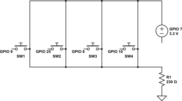
schematic

simulate this circuit – Schematic created using CircuitLab

(7) provides a 3.3V steady supply from the Raspi Zero. (8), (9), (11), (25) serve as inputs to listen to the individual button clicks.

I use this configuration (lines 52-65) for the GPIOs:

# KEYPAD PINS
# PIN layout
keypadPowerPin = 7
button1 = 11
button2 = 8
button3 = 25
button4 = 9
GPIO.setup(keypadPowerPin, GPIO.OUT)
GPIO.setup(button1, GPIO.IN, GPIO.PUD_DOWN)
GPIO.setup(button2, GPIO.IN, GPIO.PUD_DOWN)
GPIO.setup(button3, GPIO.IN, GPIO.PUD_DOWN)
GPIO.setup(button4, GPIO.IN, GPIO.PUD_DOWN)
# Power up 3.3V input pin
GPIO.output(keypadPowerPin, 1)

Edit: The listeners to actually handle input events are further down in the referenced listing (lines 344-348):

# Add keypad button handlers
GPIO.add_event_detect(button1, GPIO.RISING, callback=button_pressed_callback, bouncetime=300)
GPIO.add_event_detect(button2, GPIO.RISING, callback=button_pressed_callback, bouncetime=300)
GPIO.add_event_detect(button3, GPIO.RISING, callback=button_pressed_callback, bouncetime=300)
GPIO.add_event_detect(button4, GPIO.RISING, callback=button_pressed_callback, bouncetime=300)

Thanks!

4
  • It is far from clear what you have done. Draw a proper circuit not pictures of buttons. As far as I can see the buttons are using internal pull down which is subject to interference and for some bizarre reason using another pin for power. But no code to actually DO anything.
    – Milliways
    Commented Feb 21, 2023 at 12:10
  • It's not clear why you are powering from a GPIO. Why not use a 3V3 pin? Also it's not clear if the buttons are defaulted high or low. A proper schematic would clarify the situation.
    – joan
    Commented Feb 21, 2023 at 12:10
  • Thanks, updated the image for a schematic. I also listed the code for the handlers, which was further down in the linked python script. @Milliways the reason for using a pin as power is that the device also contains a stepper motor and a display and I was running out of pins. Could you elaborate why it is not recommended to use a GPIO as power supply?
    – m5c
    Commented Feb 21, 2023 at 12:53
  • I guess I see the main issue now though… I put the ground on the wrong side of the switches. The GPIOs are not connected to ground in default button state. I guess that’s why you meant by « subject to interference » ? @Milliways See: raspberrypi.stackexchange.com/a/69475/152237
    – m5c
    Commented Feb 21, 2023 at 13:28

2 Answers 2

0

What you have is NOT a pull down. The resistor actually does absolutely nothing (except draw current from GPIO which is close to the maximum a GPIO can safely supply).

It is normal engineering practice to use pullup and wire switches to Gnd.

See https://elinux.org/RPi_GPIO_Interface_Circuits#Buttons_and_switches

The internal pull resistors are high impedance 50k and only suitable for very short wires.

3
  • I’m unsure how to follow up on the reply. Is the message that I should change the wiring to a pull-up as referenced in the elinux link (because: « pull up is normal engineering practice while pull down is not »?). Or is the message that I merely implemented the pull down wrong by placing the grounded resistor on the wrong side of the button? Could you please clarify?
    – m5c
    Commented Feb 22, 2023 at 0:29
  • Either works (there are subtle reasons to prefer Gnd). What you have will work (remove the superfluous resistor). One way to improve noise rejection is to use low value pull. EACH pin NEEDS its own pull.
    – Milliways
    Commented Feb 22, 2023 at 0:47
  • You seem to have an issue with 3.3V pins (this depends on your wiring) Gnd is preferable.
    – Milliways
    Commented Feb 22, 2023 at 0:49
-1

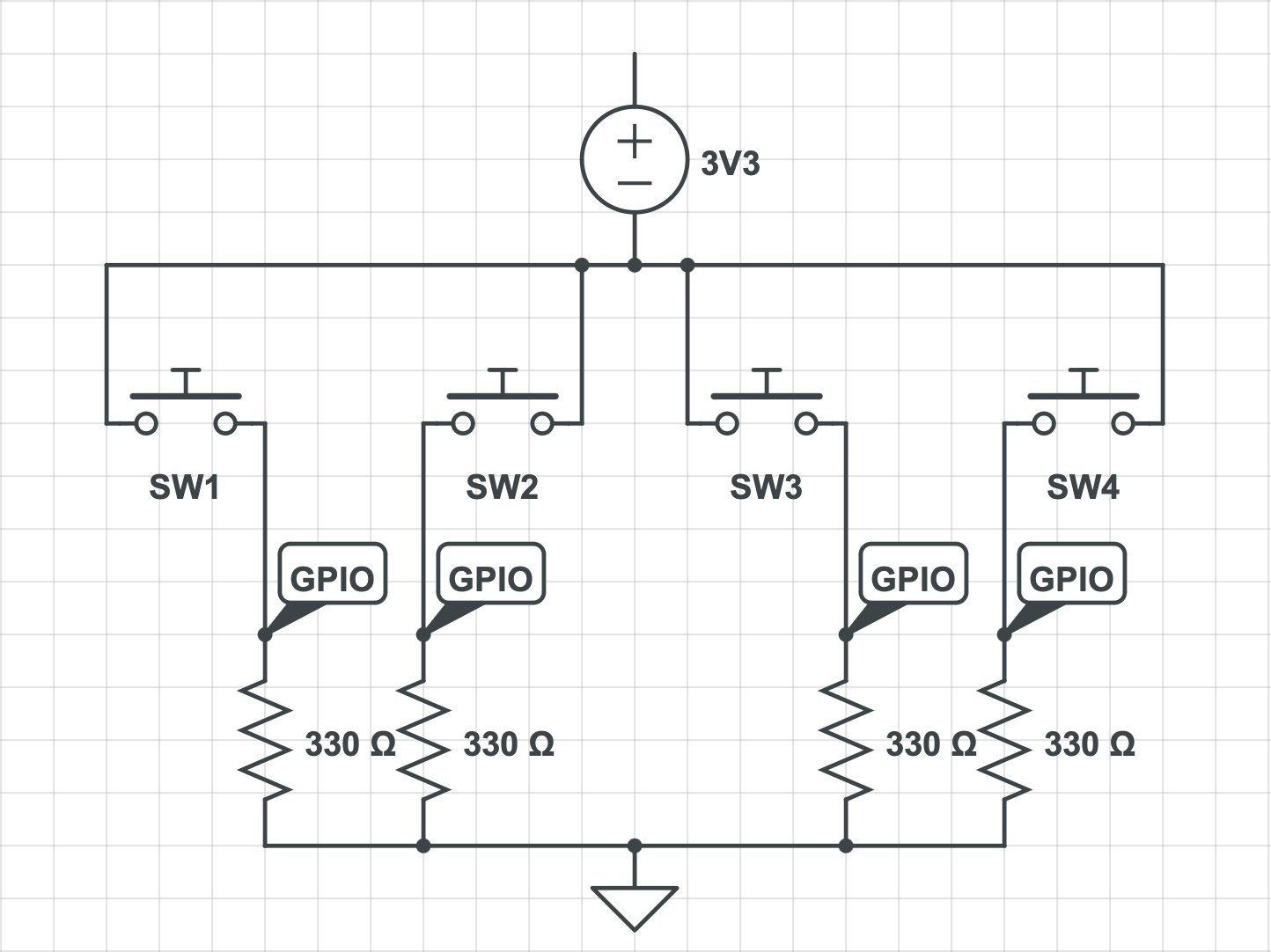
A bit belated, but I wanted to post the pull down schematic that eventually solved my issue:

enter image description here

Essentially, this circuit overcomes the "Floating" GPIOs, by adding a resistor + common GND for each GPIO. It is safe to use the same voltage supply for all buttons and use a single GND. The trick was to use separate resistors, so one button click does not impact the others.

Also, notice that as long as no button is pressed there is no closed circuit / no current.

Hope it helps someone, sometime.

1
  • this is exactly how pulldown resistors should be wired ... it is documented many times on the internet
    – jsotola
    Commented May 2 at 20:59

Your Answer

By clicking “Post Your Answer”, you agree to our terms of service and acknowledge you have read our privacy policy.

Not the answer you're looking for? Browse other questions tagged or ask your own question.