15

Expanding on this question. I am looking at a few different ways to hook up a HD44780 to the GPIO pins and the various tradeoffs.

Here's my "world clock" running off a RPi using I²C RPi running 3 HD44780 displays via I²C

So far I've just got one working using 6 GPIO pins similar to the tutorial at Adafruit and an I²C version using a MCP23017

Other ideas I would like to get working are:

The 6 GPIO pin version is simple, but uses 6 valuable GPIO pins
The CD4094 version is very cheap and only needs 2 GPIO pins
The I²C version is only slightly more expensive, but can run up to 6 displays with a single MCP23017 and share the I²C with other devices

Can anyone think of other options to try?

1
  • Have a look at this: schnatterente.net/technik/… It's a real cool RSS Reader for Raspberry Pi + HD44780 Display! :)
    – user1838
    Commented Oct 12, 2012 at 16:30

2 Answers 2

5

6 GPIO pins

Here is the code I am currently using. So far just GPIO is working. Look at the test_gpio function to see/change which GPIO pins are connected to which pins on the LCD module.

import time
import RPi.GPIO as GPIO

class LCD_GPIO(object):
    # Timing constants
    E_PULSE = 0.00005
    E_DELAY = 0.00005
    def __init__(self, RS, E, D4, D5, D6, D7):
        self.RS = RS
        self.E = E
        self.D4 = D4
        self.D5 = D5
        self.D6 = D6
        self.D7 = D7

        GPIO.setmode(GPIO.BCM)        # Use BCM GPIO numbers
        GPIO.setup(self.E, GPIO.OUT)  # E
        GPIO.setup(self.RS, GPIO.OUT) # RS
        GPIO.setup(self.D4, GPIO.OUT) # DB4
        GPIO.setup(self.D5, GPIO.OUT) # DB5
        GPIO.setup(self.D6, GPIO.OUT) # DB6
        GPIO.setup(self.D7, GPIO.OUT) # DB7

    def lcd_byte(self, data, mode):
        GPIO.output(self.RS, mode)

        for bits in (data>>4, data):
            GPIO.output(self.D4, bits&0x01)
            GPIO.output(self.D5, bits&0x02)
            GPIO.output(self.D6, bits&0x04)
            GPIO.output(self.D7, bits&0x08)

            # Toggle E
            time.sleep(self.E_DELAY)
            GPIO.output(self.E, True)
            time.sleep(self.E_PULSE)
            GPIO.output(self.E, False)
            time.sleep(self.E_DELAY)


class LCD_23017(object):
    pass

class LCD_4094(object):
    pass    

class HD47780(object):
    LCD_CHR = True
    LCD_CMD = False
    # Base addresses for lines on a 20x4 display
    LCD_BASE = 0x80, 0xC0, 0x94, 0xD4

    def __init__(self, driver, rows=2, width=16):
        self.rows = rows
        self.width = width
        self.driver = driver
        self.lcd_init()

    def lcd_init(self):
        # Initialise display
        lcd_byte = self.driver.lcd_byte
        for i in 0x33, 0x32, 0x28, 0x0C, 0x06, 0x01:
            lcd_byte(i, self.LCD_CMD)


    def lcd_string(self, message):
        # Send string to display
        lcd_byte = self.driver.lcd_byte
        lcd_byte(self.LCD_BASE[0], self.LCD_CMD)
        for i in bytearray(message.ljust(self.width)):
            lcd_byte(i, self.LCD_CHR)

def test_gpio():
    driver = LCD_GPIO(RS=7, E=8, D4=25, D5=24, D6=23, D7=18)
    lcd = HD47780(driver=driver, rows=4, width=20)
    lcd.lcd_string("Welcome gnibbler")


def main():
    test_gpio()

if __name__ == "__main__":
    main()
5

I²C

Hooking it up is fairly straightforward. The contrast pin(VO) of the particular displays I am using needs to be connected to ground. Usually you would connect it to a potentiometer to set the voltage between VSS and VCC

My displays don't have a backlight, so I haven't connected those to reduce clutter on the schematic. If yours has a backlight you should of course connect it in the usual way

You can connect up to 3 displays in parallel to each port of the MCP23017. The only difference is the enable pin from each display needs to connect to a separate pin (GPB1-GPB3)
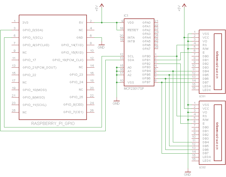
Raspberry Pi driving HD44780 via MCP23017

#!/usr/bin/env python
"""World Clock Demo
   It should be fairly obvious how to change this code to work for other timezones"""
import time

class LCD_23017(object):
    # Timing constants
    E_PULSE = 0.00005
    E_DELAY = 0.00005
    def __init__(self, bus, addr, port, rs, en):
        self.bus = bus
        self.addr = addr
        self.rs = rs
        self.en = en

        self.DIRECTION = 0x00 if port == 'A' else 0x01
        self.DATA = 0x12 if port == 'A' else 0x13

        self.bus.write_byte_data(addr, self.DIRECTION, 0x00)

    def lcd_byte(self, data, rs):
        rs <<= self.rs
        en = 1 << self.en
        for nybble in (data&0xf0, data<<4):
            self.bus.write_byte_data(self.addr, self.DATA, nybble | rs)
            time.sleep(self.E_DELAY)
            self.bus.write_byte_data(self.addr, self.DATA, nybble | rs | en)
            time.sleep(self.E_PULSE)
            self.bus.write_byte_data(self.addr, self.DATA, nybble | rs)


class HD47780(object):
    LCD_CHR = True
    LCD_CMD = False
    # Base addresses for lines on a 20x4 display
    LCD_BASE = 0x80, 0xC0, 0x94, 0xD4

    def __init__(self, driver, rows=2, width=16):
        self.rows = rows
        self.width = width
        self.driver = driver
        self.lcd_init()

    def lcd_init(self):
        # Initialise display
        lcd_byte = self.driver.lcd_byte
        for i in 0x33, 0x32, 0x28, 0x0C, 0x06, 0x01:
            lcd_byte(i, self.LCD_CMD)

    def lcd_string(self, message, line=0):
        # Send string to display
        lcd_byte = self.driver.lcd_byte
        lcd_byte(self.LCD_BASE[line], self.LCD_CMD)
        for i in bytearray(message.ljust(self.width)):
            lcd_byte(i, self.LCD_CHR)


def test_i2c():
    from datetime import datetime
    import pytz
    import smbus

    ## For Rev1.0 Raspberry Pi
    driver1 = LCD_23017(bus=smbus.SMBus(0), addr=0x27, port='B', rs=0, en=1)
    driver2 = LCD_23017(bus=smbus.SMBus(0), addr=0x27, port='B', rs=0, en=2)
    driver3 = LCD_23017(bus=smbus.SMBus(0), addr=0x27, port='B', rs=0, en=3)

    ## For Rev2.0 Raspberry Pi
    #driver1 = LCD_23017(bus=smbus.SMBus(1), addr=0x27, port='B', rs=0, en=1)
    #driver2 = LCD_23017(bus=smbus.SMBus(1), addr=0x27, port='B', rs=0, en=2)
    #driver3 = LCD_23017(bus=smbus.SMBus(1), addr=0x27, port='B', rs=0, en=3)


    lcd1 = HD47780(driver=driver1, rows=2, width=16)
    lcd2 = HD47780(driver=driver2, rows=2, width=16)
    lcd3 = HD47780(driver=driver3, rows=2, width=16)
    lcd1.lcd_string("    New York")
    lcd2.lcd_string("     London")
    lcd3.lcd_string("    Melbourne")
    new_york_tz = pytz.timezone("America/New_York")
    london_tz = pytz.timezone("Europe/London")
    melbourne_tz = pytz.timezone("Australia/Melbourne")
    while True:
        time.sleep(1-time.time()%1)  # Wait until the next second
        lcd1.lcd_string(datetime.now(new_york_tz).ctime()[3:], line=1)
        lcd2.lcd_string(datetime.now(london_tz).ctime()[3:], line=1)
        lcd3.lcd_string(datetime.now(melbourne_tz).ctime()[3:], line=1)

def main():
    test_i2c()

if __name__ == "__main__":
    main()
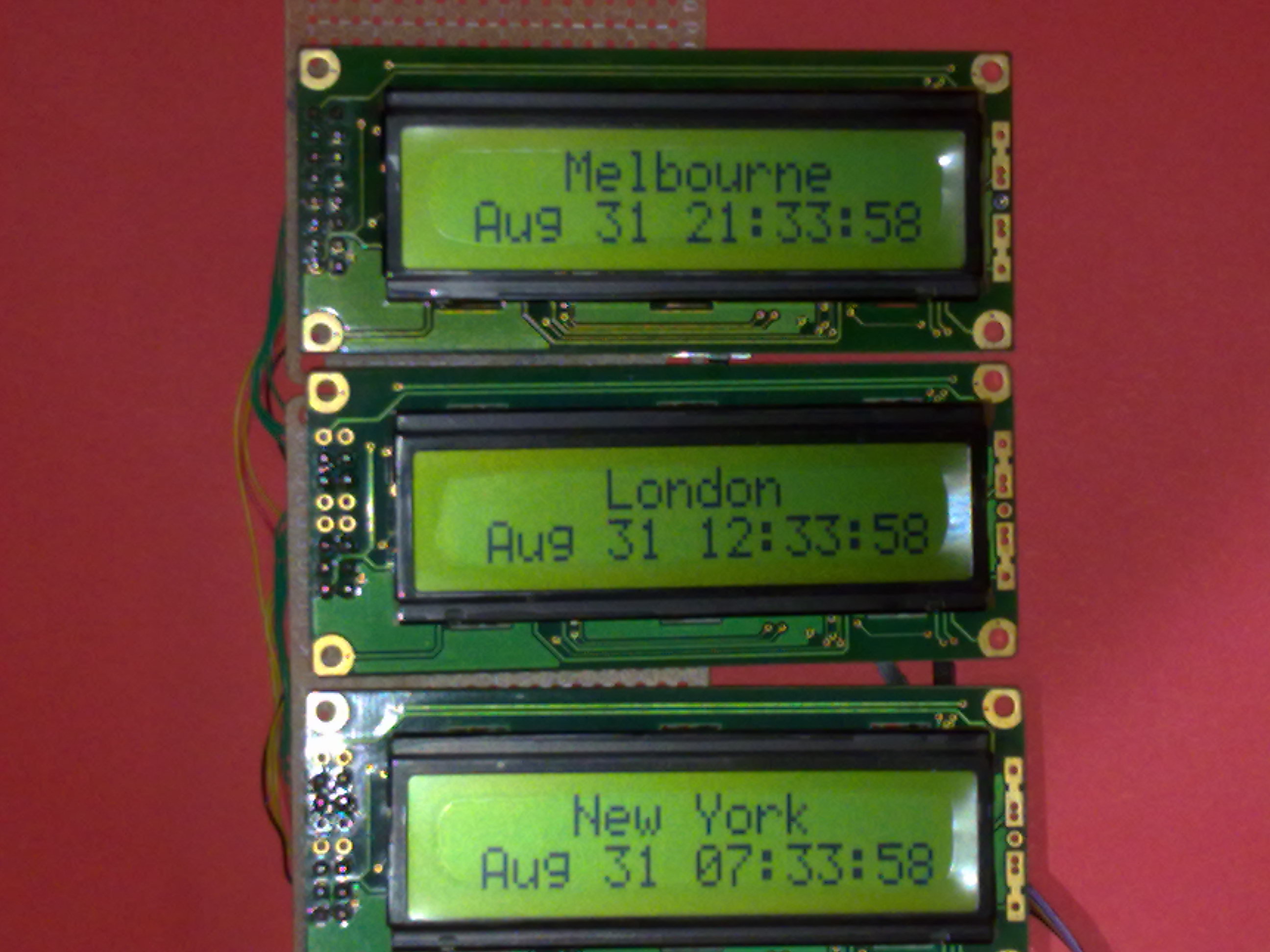
1
  • Thanks. It works!. This great post helps me a lot. Only a comment for newbies (like me). If you use a Raspberry Rev.2, use bus=smbus.SMBus(1) instead of bus=smbus.SMBus(0) in the code. The adress can be determined by running this command: "sudo i2cdetect -y 1" (use 0 instead 1 for Raspberry Rev.1). In my case was 0x20 instead of 0x27. Thanks a lot.
    – user9457
    Commented Sep 10, 2013 at 18:19

Your Answer

By clicking “Post Your Answer”, you agree to our terms of service and acknowledge you have read our privacy policy.

Not the answer you're looking for? Browse other questions tagged or ask your own question.