1

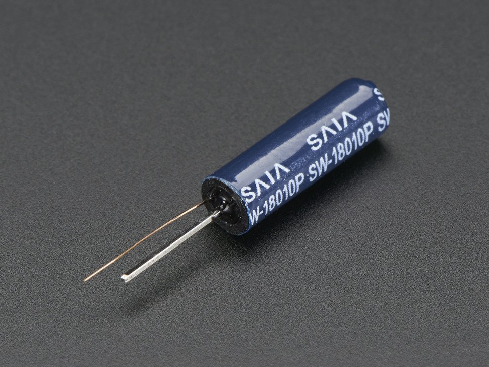
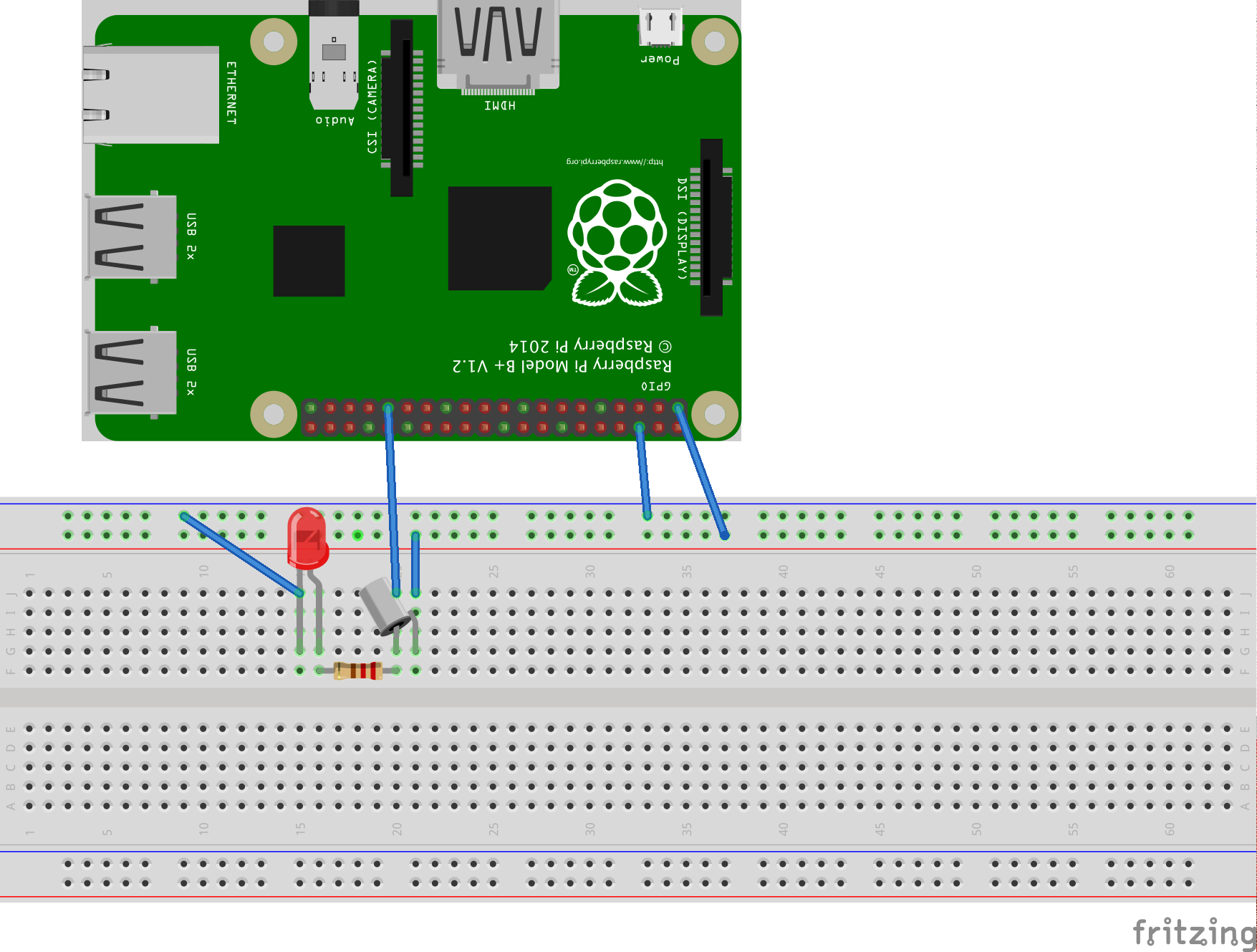
I am trying to use a vibration sensor with my Raspberry Pi. The wiring looks like this:

3.3V -> VIBRATION SENSOR -> LED (Grounded) -> GPIO6

Whenever I touch the vibration sensor, the led goes on.

I wrote the following script:

from time import sleep
import RPi.GPIO as GPIO

GPIO.setmode(GPIO.BCM)
GPIO.setup(6, GPIO.IN)
sleep(0.1)

while True:
    result = GPIO.input(6)
    if result == 1:
        print("Vibrated")

The problem is that I am getting tons of vibration even when nothing touches the sensor (the LED is off).

What I am doing wrong here? I would expect the GPIO to report high only when a 3.3V current flows through the wire.

enter image description here

enter image description here

2
  • Does your sensor have an potentiometer built in for adjustments? Please link to the exact sensor you have. Commented Oct 13, 2015 at 14:11
  • I have just added the pictures of my circuit and the component. Thanks
    – Jay CCC
    Commented Oct 14, 2015 at 6:41

1 Answer 1

3

What you are likely seeing is the result of your SENSOR->LED->GPIO6 line being in a "floating" state - it is not part of an active circuit and hence the voltage on the line is fluctuating.

You will need to enable the pull-down resistor on GPIO6 by replacing

GPIO.setup(6, GPIO.IN)

with

GPIO.setup(6, GPIO.IN, pull_up_down=GPIO.PUD_DOWN)

A pulldown resistor basically ensures that if the line is floating, it will get connected to Ground (0V) and always read LOW. Similarly, using a pullup resistor ensures that if the line is floating, it will get connected to 3V3 and always read HIGH. The value of the resistor is high enough (in the order of 50kOhm) to effectively block the path to 0V/3V3 once the line is connected to a circuit, current is flowing and the line no longer floats.

5
  • Hi Phil. Now the GPIO is high all the time. :-(
    – Jay CCC
    Commented Oct 13, 2015 at 14:02
  • Argh - sorry, replace "GPIO.PUD_UP" with "GPIO.PUD_DOWN" - copy&paste error on my end - I've changed it in my answer.
    – Phil B.
    Commented Oct 13, 2015 at 14:03
  • Hi Phil, it is either HIGH all the time or LOW all the time depending on the PUD_UP or PUD_DOWN. I have edited my question with new pictures. Thanks
    – Jay CCC
    Commented Oct 14, 2015 at 6:42
  • It would be better to post a schematic instead of a picture of a breadboard with wires that are difficult to trace (check out Fritzing if you don't have software to make schematics). Do I read correctly that you have an LED connected to ground in your circuit? What happens if you remove that ground connection and just put the LED in the 3V3->SENSOR->LED->GPIO circuit, without a separate connection to ground? And what is the function of the resistor - is this in combination with your LED? If so, it should be in series with the LED, not in parallel.
    – Phil B.
    Commented Oct 14, 2015 at 12:16
  • 1
    Thank you very much Phil not only for helping me out with the circuit but also the Fritzing advice! Very nice software btw.
    – Jay CCC
    Commented Oct 16, 2015 at 16:11

Your Answer

By clicking “Post Your Answer”, you agree to our terms of service and acknowledge you have read our privacy policy.

Not the answer you're looking for? Browse other questions tagged or ask your own question.