2

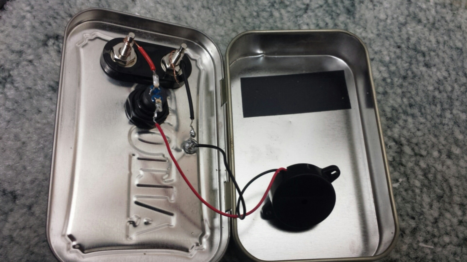
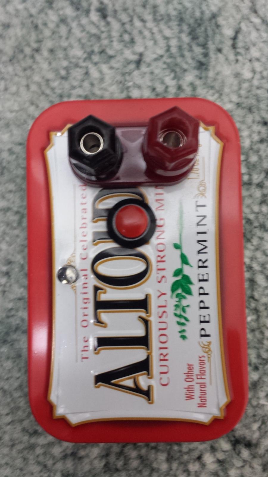
I have built a small Morse code key that consists of a push button, a 3v buzzer and an LED. When I connect the positive side to 3v3 and the negative side to ground, the key works. I push on the button, the buzzer sounds and the LED illuminates. Constant 3.3v across the circuit when checked with a multimeter.

I wrote a program that uses the button presses to generate dots and dashes. GPIO 11 is set as an input that uses the pull up resistor. When I jump wires across GPIO 11 and ground, it works fine, constant 3.3v.

However, when I connect the positive side of the key to GPIO 11 and the negative side to ground, when I press the button the LED barely lights, the buzzer crackles softly and the pi doesn't see GPIO 11 As having gone high. When tested with a multimeter, I have 3.3v from GPIO 11 to ground when the button is open, but only 2.17v when the button is closed. The resistance of the circuit is ~4 ohms.

What is the next step in troubleshooting?

Photos of device:

enter image description here

8
  • Try a different button.
    – goobering
    Commented Feb 18, 2016 at 15:07
  • What would cause the current button to work from 3v3 to ground, but not GPIO 11 to ground? Commented Feb 18, 2016 at 15:14
  • No idea. But if you don't rule it out as a possibility then it remains a factor.
    – goobering
    Commented Feb 18, 2016 at 15:15
  • The next step in troubleshooting would be to edit the question and replace the word "piss" then include a picture of your setup/circuit in the question. Max file size cannot exceed 2MB.
    – Aloha
    Commented Feb 18, 2016 at 15:31
  • 1
    De-bounce your push button in the software ?
    – Marla
    Commented Feb 18, 2016 at 16:08

2 Answers 2

3

The GPIO pin cannot provide enough current to drive the buzzer and the LED.

Change your circuit to use a double pole switch with one pole connected to the 3.3V pin to drive the buzzer and LED and the other connected to the GPIO for the Raspberry Pi to read the button state.

1
  • This may seem like a dumb question, but I'm rather new to EE. Would it be possible to feed the positive terminal from GPIO 11 and the 3v3 pin? Could i damage the pi? If so, could I solder a diode into the wire going to GPIO 11 to prevent the 3v3 from backfeeding? Commented Feb 18, 2016 at 19:46
1

Solution:

I went to radio shack for a DPDT switch. They didn't have any, and I needed to have this project finished by this weekend. I decided to use an NPN transistor, so that the circuit I have currently fed the base of the transistor, using it to switch the logic portion of the circuit. Wired it up using a bread board, it works beautifully.

I have to find a way to integrate two more wires, but that's a small price to pay for it doing exactly what I want it to.

Your Answer

By clicking “Post Your Answer”, you agree to our terms of service and acknowledge you have read our privacy policy.

Not the answer you're looking for? Browse other questions tagged or ask your own question.