3

I'm currently designing a PCB with some fets, logic level shifting and RS-232 connectors, to use with my Raspberry Pi 2. Now I thought, I could add a (around) 24v to 5v supply circuit, to directly power the raspberry pi on it's 5v (out) pin.

However, if I'm going to power it through the 5v pin, I'm bypassing all voltage protection circuitry. Which would be bad.

I could probably drop in a 24v to 5v regulator, but would I still need:

  • Power reverse protection (swapping 5v and GND)
  • Over voltage protection (hooking up the 24v to the 5v output? xD)
  • Over current protection (shorts-circuit?)
  • Smoothing capacitors ?

I'm also not a 100% sure what type of converter I need:

  • Buck, UBEC?
  • regulated (probably?)
  • switching or lineair?
  • Placeable on PCB or as a loose (screw able) part (is one better as the other?)
  • However the other side is 24V I'm not a 100% on how accurate it is. It also has some high-current relaises (does these matter? I wouldn't want the RPI to get blown up, or lose power/voltage.)

I'm looking at a current draw of around 3A max, more is always good :)

I'm not really looking for shopping recommendations, but more of a general help/explanation on what things I should look out for.

6
  • Might it be easier to replace the existing micro USB socket with a hookup to your 5V regulator, or identify another suitable point before the Pi's own protection devices where you could apply your 5V?
    – goobering
    Commented Feb 25, 2016 at 14:27
  • 2
    I know this is a total hack solution (hackier than goobering's) and I haven't tried it yet myself (I'm thinking about it for something), but: Why not just cut off a micro-USB adapter and attach the appropriate leads to an ~5V supply, then plug that into the pi (obvious disadvantage is it takes up space)?
    – goldilocks
    Commented Feb 25, 2016 at 14:30
  • I've done that more than once. Works fine/looks messy. :)
    – goobering
    Commented Feb 25, 2016 at 14:30
  • @goldilocks, I actually considered that (and should have mentioned). I skipped that option after I couldn't find any "microusb screwterminal connectors". Good solution, but I want to use it in a "industrial" application where I use a DIN rail with an enclosure. It might not have that much room at the side and those USB connector is a bit loose.
    – aaa
    Commented Feb 25, 2016 at 16:04
  • And I was thinking of using a 24V supply, which won't do over the USB in. But by combining Joans' answer and your, it might actually work reasonable.
    – aaa
    Commented Feb 25, 2016 at 16:07

4 Answers 4

6

I use UBECs to power several of my Pis.

You can get UBECs to switch anything in the range 9V-26V to 5V at 3 amp for a couple of UK £.

If you are worried about no protection then just feed the UBEC output into the microUSB power input.

2
  • Hmm, I found some 90 degree angle USB connectors, which take away the "space restrictions", so this is actually a pretty good answer! You think it would do any harm to have the UBEC power the 5V pin directly? (But yeah, why bother, the 90 degree connector seems to resolve the biggest issue.
    – aaa
    Commented Feb 25, 2016 at 16:09
  • @Paul Powering directly on the 5v pin is so tempting but I suggest you don't do it. I fried my brand new Pi 3 that way...it worked for a couple of weeks but then one day it suddenly died. Just be careful :-). My UBEC was a good one too, that other Pi owners had used.
    – NULL
    Commented Jul 18, 2016 at 20:18
3

I'm designing a system that will power a 2B using an OKI-78SR-5/1.5. It's a switching regulator, pin-for-pin compatible with the classic 7805 linear regulator. I'll be using a 15V PSU (for a motor) and once connected it will stay connected. So after some fairly basic testing I'm just planning on being careful to connect it the right way round. This only does 1.5A, but do you really need more than that on the Pi PCB?

If you've got further significant 5V power requirements I'd be very tempted to run them separately -- I've crashed a Pi a few times by connecting a not-very-big capacitor to the 5V line using the official 2A PSU, so inrush currents are something to be wary of. They happen fast enough that no reasonable fuse could blow/trip fast enough to prevent a dip in voltage for a big enough surge load so are hard to protect against. Even though I'm guilty of it, I don't recommend plugging anything in while powered up.

I'm not sure what current the PCB traces and headers are rated for, but for large 5V loads you may reach the limit. So there are two reasons to separate the 5V supplies to the Pi and other hardware, even if it's not a situation where isolation is required. One decent 5V supply could even feed both the Pi and the accessories, but I'd run independent cables back to the power supply with capacitors at the power supply output and the Pi input.

7
  • Hmm, so the boards are not even 100% safe by design (no inrush/over current protection), that's very usefull to know! I can't get 3A out of the 5V pin? Then I would indeed need a seperate current loop. But that makes it even less likely to use the USB connection.
    – aaa
    Commented Feb 25, 2016 at 17:03
  • 1
    @Paul, how would you protect against an undefined current sink except by shutting down? I'm not sure what the headers/traces are rated to but I wouldn't run 3A from the USB to the power pin -- instead I'd power through the pin and route most of the current off the Pi PCB.
    – Chris H
    Commented Feb 25, 2016 at 17:06
  • 1
    @Paul that would be reasonable though I reckon it would be hard to choose one that would blow/trip fast enough to prevent a crash for a big enough surge load. Even though I'm guilty of it, I don't recommend plugging anything in while powered up.
    – Chris H
    Commented Feb 25, 2016 at 18:10
  • 1
    You could go either way. But the gate on a FET should draw so little current that you can put a big resistor in between. Perhaps with another resistor to ground such that even if you got 24V on the gate your GPIO (assumed) would only see 3V. Check datasheets etc. Solid state relays combine FETs with opto-isolation in one package. You may find one suitable but check the current at 3.3V
    – Chris H
    Commented Feb 25, 2016 at 18:23
  • 1
    That's indeed a whole other question and I have to switch spotlights which can temporarily draw an awfull lot of current. So I'll have to dig into the specifics for that. Thank you for your help!
    – aaa
    Commented Feb 25, 2016 at 18:26
2

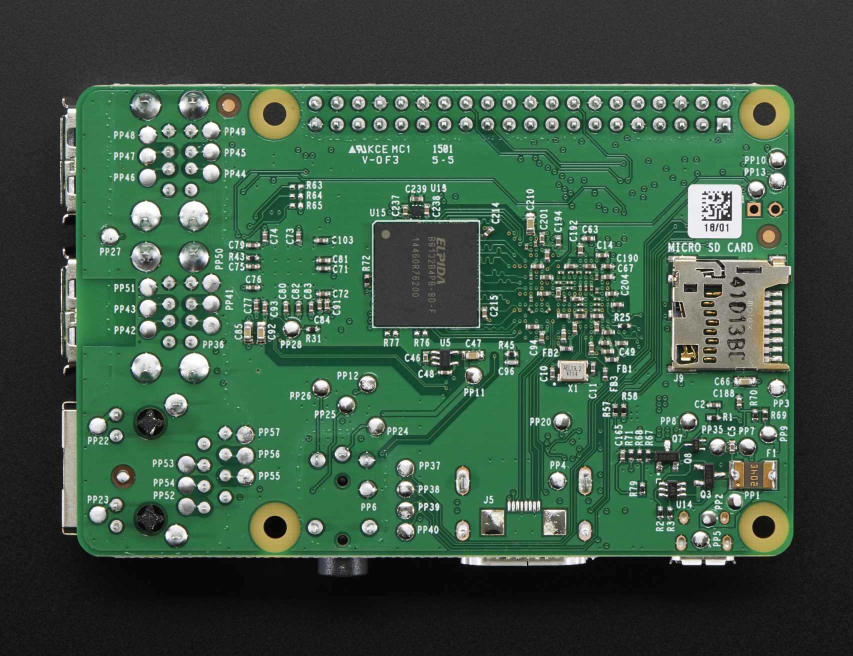
This thread on the raspberrypi.org forums suggests that pads PP1/PP2 (5V) and PP3 (ground) can be used to safely apply 5V to the Pi. This doesn't require removing the USB socket or using a micro USB plug, and retains all of the Pi's protection capabilities.

Underside of Raspberry Pi 2

PP1 and PP2 are in the bottom right corner of the board as seen above, with PP3 at the extreme right of the board directly below the micro SD card slot. It may be challenging to solder wires directly to these points while maintaining some kind of strain relief. Lots of hot glue may (as ever) be your friend. As long as your power supply conforms to the usual standards for use with a Pi (4.75V - 5.25V) this approach should work fine.

1
  • Hmm, the idea was to avoid soldering and external connections. But an interesting answer with source that gives another option is always good. I found out that I'd better use the a separate loop for driving the relays also.
    – aaa
    Commented Feb 25, 2016 at 17:23
1

FWIW I've powered multiple Pi's directly onto the 5 volt pin with UBEC's. If you want to be careful about the cleanliness of the power you could always put a 7805 or similar regulator on the output of the UBEC to smooth out the power without having the overheating problems inherent to passing lots of current through a linear regulator.FWIW I've powered multiple Pi's directly onto the 5 volt pin with UBEC's. If you want to be careful about the cleanliness of the power you could always put a 7805 or similar regulator on the output of the UBEC to smooth out the power without having the overheating problems inherent to passing lots of current through a linear regulator.

2
  • That's an interesting idea! It does not add any protection, only smoothing? I do have a big capacitor on the power supply, but guess I could just test it out actually.
    – aaa
    Commented Feb 25, 2016 at 18:59
  • @Paul Though your capacitor would probably be sufficient, it would probably add quite a bit of protection, actually. The linear regulator could work on its own, in fact, but those kinds of regulators get really hot and inefficient when regulating a lot of current down from a higher voltage. Using the UBEC to do the heavy lifting and putting the linear regulator after gives you the best of both worlds. Commented Feb 25, 2016 at 19:29

Your Answer

By clicking “Post Your Answer”, you agree to our terms of service and acknowledge you have read our privacy policy.

Not the answer you're looking for? Browse other questions tagged or ask your own question.