So I had the GPIO diagram upside down (haha). SO I connected the 5V Power pin on the header to the 3.3V Power pin on the GPIO. It was only for a second or less. My RPi still works fine, but I wonder if I should now consider this board suspect?
-
I can't imagine any situation which would require connecting 2 Pi expansion connector (not GPIO) pins together or how having the diagram upside down would connect a expansion connector 3.3V to 5V so it is difficult to make any sensible comment.– MilliwaysCommented Jun 6, 2016 at 12:11
-
1Not to say that it couldn't cause harm, but if everything is currently working you probably got lucky. It is not a conventional short.– goldilocks ♦Commented Jun 6, 2016 at 12:31
-
1Thanks for the responses. To clarify, I was trying to connect header pin #39 to header pin #40. If done correctly, this connects GPIO21 to GND. But instead I connected header pin #1 to header pin #2, this connects the 5v output to the 3.3v output. Was wondering if anyone knew for sure if the 3.3v output has defenses that can cope with having 5v forced down its throat.– MikeCommented Jun 7, 2016 at 4:40
-
1+1 on that question! I connected 5V output of a board (16-Channel 12V Relay Module) to 3.3V output of Pi. Gnd was also connected to Gnd. It stayed connected for several secons.– visoftCommented Nov 17, 2017 at 11:07
-
@visoft - Tell us about it - with pictures - and perhaps you too could gain an un-coveted rip tag...!– SlySvenCommented Dec 15, 2018 at 0:05
2 Answers
Did any of the magic blue smoke get out? Also, what was on the other end of the lead that you were connecting to the RPi's GPIO Header? Those supplies on pins 1 and 2 (the end away from the Ethernet/USB connectors are normally to supply power to connected hardware (but the 5V can be used as a power input to the RPi - I have a RPi specific UPS that does that). Depending on what the connected stuff was you might have got away with it provided that the ground connections further towards the middle did not short out the RPi GPIO pins that actually connect to I/O lines on the SoC if they too got swapped over.
Perhaps after this time you are in a better position to judge. If you can come back to us you on this you may be in-line to get a rip tag for this question - as it is I guess this rates an honourable mention! 8-)
1) Take a multimeter and measure 5 volts on the fuse. Both fuse contacts should show the same value
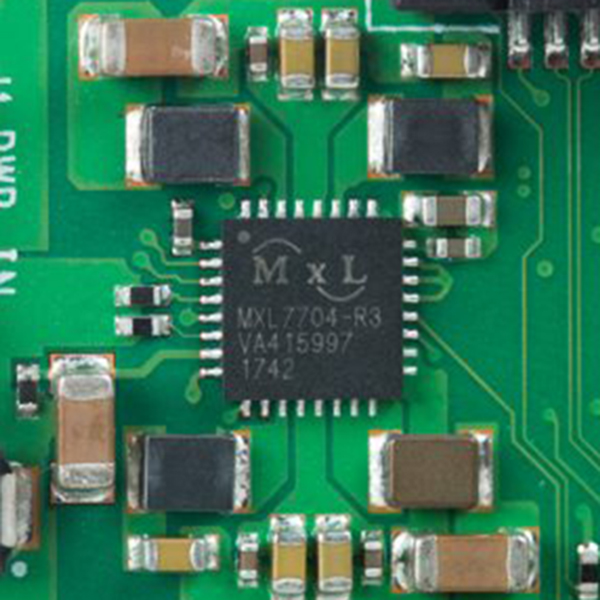
2) Find the MxL7704 chip board and measure the output volts
good video explanation for this: https://www.youtube.com/watch?v=Hunm5S94BaE
Also, to avoid damage to the Raspberry Pi, use an additional separate power supply.
If you accidentally shorted 3.3 volts to the GND and the voltage regulator failed you can buy a new regulator online for $ 3.5 and pay for repair or repair yourself.
Update 23-02-2020:
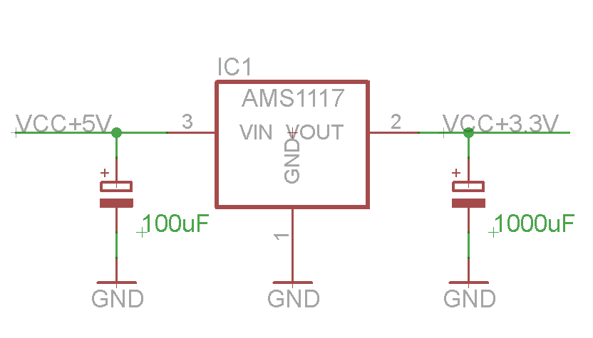
Theoretically as far as i can remember 5 volts goes straight from the power supply to the GPIO raspberry pi. And 3.3 volts goes through the voltage regulator (for example MXL7704-r3) which burns at the closing of 3.3 volts + GND. To prevent the voltage regulator (for example MXL7704-r3) from malfunctioning, do not use 3.3 volts on the Raspberry pi GPIO and instead use a 5 volt to 3.3 converter. For example: 
-
Are you shure that a russian speaking video is a good explanation?– MatsKCommented Oct 7, 2019 at 17:30
-
For people who want to repair with their own hands will be enough of this video and automatic subtitles. To complete the repair, a person must already have some skills. The new voltage regulator costs $ 3.5. So I think this answer will help someone in the future.– snexCommented Oct 8, 2019 at 11:38

