1

Preamble:

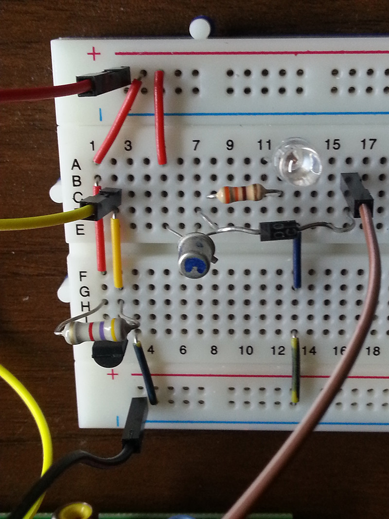
  • Red Wire: from 3.3v of Raspberry
  • Black Wire: ground from Raspberry
  • Yellow: PIN 1-Wire (as IN) from Raspberry (7th?)
  • Brown: PIN 17 (as OUT) from Raspbery

Circuit

The pull-up resistor used to drive the DS1820 is a 4.7K.

On the 17 PIN of the Raspi I connected the base of a 2N2222A (diode only for testing, later I will connect a relay).

The GPIO 17 pin is configured as an output pin, so it can drive current through the base of the transistor, thus lighting the LED.

The sensor functions perfectly and I can monitor the ambient temperature very well. A bash script checks if the room temperature reaches >= 28°. In that case the LED is on, otherwise the LED is off.

Here are my questions:

  1. Is the LED (circuit) in parallel with the DS1820 (circuit)?
  2. The LED is quite dim. If I leave out the 330 resistor, the LED is very bright (and not burning).
  3. Since I have 2 circuits (LED + DS1820) and I am driving the LED with a 300 Ohm resistor, do I need to change the resistor at the DS1820 or is it drawing the right current?
  4. What kind of tests do you recommend? (E.g. "Measure the current between X and Y, if it is > of xxxA then.........") etc etc.

1 Answer 1

1
  1. Yes, the LED circuit is in parallel with the DS1820 circuit because they are are only connected with each other at 3.3V and GND.
  2. A 300 Ohm resistor @3.3V limits the drawn current to 3.3V / 300 Ohms = 11 mA (Ohm's law: I = U / R). Usually, LEDs draw about 20mA of current. That's why it's a bit dim. LEDs shouldn't be driven without resistors, though (safety first).
  3. The circuits are parallel and therefore shouldn't influence each other and no changes are required. The 4.7k resistor is a pull-up resistor for the digital DATA line. Its function is to provide 3.3V to the DATA pin when no signal is transferred between DS1820 and RPi. If omitted, the voltage between DATA and GND could be anything between 0 and 3.3V, which could cause trouble.
  4. You could measure in series (!!!) between any two components on the 3.3V rai but it's not really necessary. If you really want to do it, remove the red wires that go from 3.3V to row 5 and 7 and replace them with your multimeter probes.

The Raspberry's GPIO pins can each handle up to 16mA of current. However, you should not draw more that 50mA in total from the 3.3V. For example, don't try to drive 3 LEDs without resistors!
If you exceed the maximum current up, the GPIO pins will die instantly and forever, so as long as it still works you are fine.

Your Answer

By clicking “Post Your Answer”, you agree to our terms of service and acknowledge you have read our privacy policy.

Not the answer you're looking for? Browse other questions tagged or ask your own question.