2

I'm fairly new to electronics and I'm in the process of creating a IR Birdbox using a Pi Zero and IR Camera. I have a quick question regarding the correct usage of Resistors for IR LEDs (Or any LEDs for that matter!).

This is the Spec of the IR LEDs that i have:

Lenses Type : Crystal Clear Case Style : 5mm Round Forward Voltage : 1.5v - 1.6v Forward Current : 60mA Wavelength : 940nm Viewing Angle : 25deg

And my understanding is that the Raspberry Pi GPIO Pins have an output of 3.3 Volts. So using Ohms law (http://www.ohmslawcalculator.com/ohms-law-calculator) I have put in the Pi Voltage and Forward Current of the LEDs and it calculates i need a 55ohms resistor? Is this correct?

Also if i use two LEDs do i need to resistors?

Thanks and apologies if this is a reasonably basic question

Thanks and Kind Regards

7
  • 1
    The current limit of the GPIO (16 mA per pin, 50 mA in total, see here) is prohibitive to this approach. You should not connect those LEDs directly to the GPIO pins but via a driver (either a transistor + series resistor or a current source).
    – Ghanima
    Commented Sep 9, 2016 at 10:49
  • You need a series resistor per LED. The resistors main purpose is to stop the LED burning out through over current.
    – joan
    Commented Sep 9, 2016 at 10:51
  • ... and the calculation (if the current would be supplied) is not correct. You need to consider not the 3.3V for calculation but the difference between 3.3V and the forward voltage of the LEDs. That leads to a resistor of about 28 Ohms. See also: ledcalc.com
    – Ghanima
    Commented Sep 9, 2016 at 10:52
  • WRT @joan 's comment. If you intend to wire two LED in parallel both should get their own resistor. If the LED can be wired in series one resistor is fine - this however requires a supply voltage sufficiently higher than the doubled forward voltage. Worth to consider since the direct driving from the 3V3 GPIO pin is off the table anyways.
    – Ghanima
    Commented Sep 9, 2016 at 10:56
  • The above comments are all relevant, however they fail to ask what you are trying to achieve. Do you need to control the LED with the Pi or just run continuously? If you want to control you need a driver (transistor, MOSFET or buffer IC). Either way you would be better powering the LED from 5V.
    – Milliways
    Commented Sep 9, 2016 at 11:17

1 Answer 1

2

As others have pointed out, you should not try and draw 60 mA from a GPIO.

You could try and do it with a resistor that will limit the current to ~20-25 mA -- although the normal recommended maximum is 16mA, they are probably capable of nearly double that. But this is still your judgement call, and the total number of GPIOs used that way is open to question (I've done four, totalling 80-100 mA). However, if they are really intended for 60 mA, chances are this is going to very significantly reduce their brightness.

If you wanted to test this, then you could try:

(3.3 - 1.6) V / 0.02 A = 85 Ohms

This is the supply voltage minus the forward voltage drop of the LED divided by the maximum current in amps.

Making that 100 Ohms will mean the current is 0.017 A; this probably won't be much difference.

For contrast, you can connect one directly to a 3.3V pin in series with a 25-30 Ohm resistor, which should give you ~60 mA, or a 5V pin with a ~55 Ohm resistor.

(5 - 1.6) V / 0.06 A = 56.666 Ohms

However, chances are you want to connect more than two LEDs; assuming using the GPIOs are no good period, then you have a problem: You cannot control the 3.3V or 5V rail pins directly. They are on while the pi is plugged in.

If that is still okay, then you must connect the LEDs in parallel, because the forward voltage drop of the LEDs is additive in series. So likely you could hook two of them in series to 5V:

(5 - 1.6 * 2) / 0.06 = 30 Ohms

Of course, this still only gives you two LEDs. However, you can get a lot more than that by connecting them in parallel. You can actually combine the methodologies:
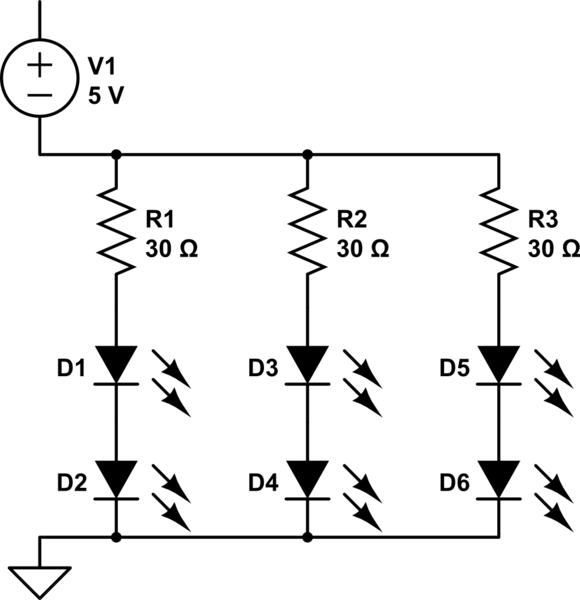
schematic

simulate this circuit – Schematic created using CircuitLab

So this is 6 LEDs in three parallel banks of two; each bank consists of a 30 Ohm resistor and two LEDs. Doing them this way instead of one LED per bank (which is the most you could get on a 3.3V pin) means that you are consuming less current, because each bank still only draws 60 mA. Presuming you have a 2A supply to the Pi, you should be safe running at least 10 of those from the 5V rail, which is probably more you need.

On new models of pi, the 3.3V rail should be good for this as well -- but I am not positive this actually includes the Zero, and in any case, because of the potential of using 2 LEDs in series, 5V is a better choice here.

This still leaves you with the issue of the LEDs being on all the time, although the total power consumption is probably < 1 W since each of those banks uses:

(5 - 3.2) V * 0.06 A = 0.1 watts

Note that you could control each bank individually, but in this case it sounds like that is not necessary, so you would instead control the whole thing using a single transistor. However, you might want to consider the use of a ULN2xxx type integrated circuit; these are at most only a few bucks a piece (although you probably have to buy 5 or 10) and allow you the option of controlling each bank.

They control via the ground, i.e., in the above circuit the second resistor of each bank would be connected to an a pin on the ULN's output side, and the 5V supply would be routed through it. The pins on the other side of the DIP are connected directly to GPIOs on the pi to turn each bank on or off.

I've run arrays of smaller LEDs using a ULN2803APG from the 3.3V rail this way before.

3
  • Hey, Wow thanks for such a great response and making everything alot clearer! Relatively new to all this and wasn't aware on the limitation of the current of GPIOs and IR Leds, I had assumed they would work just like normal LEDs! Again thanks for your help and i will look into the solutions you gave me!
    – 4dogsofwar
    Commented Sep 9, 2016 at 15:11
  • I didn't know anything about circuits before I had a pi so it is still easy for me to perceive what's potentially confusing to someone in the same position. The math and concepts above are not very complicated, but I had to do some hands on experimentation before I was confident about them -- and I have experimented with all the above. IR leds do work just like normal LEDs, but they tend to have a lower forward voltage drop (a commonplace blue or white led will have a drop > 2.5V so you couldn't pair them up like this), and at 60 mA yours are bigger than most visible light ones.
    – goldilocks
    Commented Sep 9, 2016 at 15:16
  • Thanks again for your help! Also gave me hope that all is not lost yet learning electronics! :D
    – 4dogsofwar
    Commented Sep 9, 2016 at 15:20

Your Answer

By clicking “Post Your Answer”, you agree to our terms of service and acknowledge you have read our privacy policy.

Not the answer you're looking for? Browse other questions tagged or ask your own question.