2

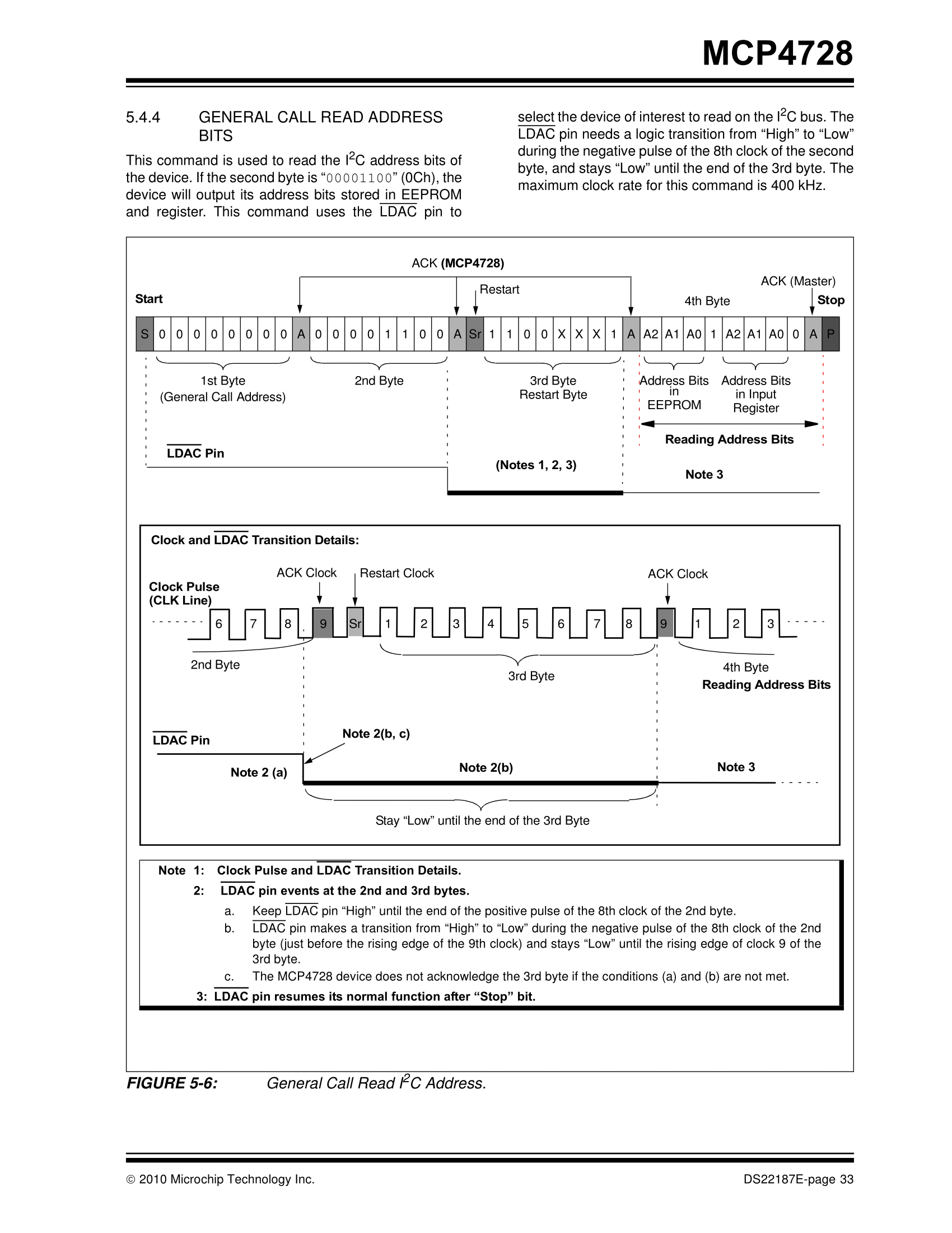
I am trying to read/update I2C address of a device. However, in order to do that during the communication state of pin LDAC has to be changed, as shown in the manual:

enter image description here

Is that possible to do with smbus package? I would look for the answer myself, but I couldn't find any instructions.

EDIT:

The problem is finally solved. You can find the library with read/update I2C address for MCP4728 on http://www.pinteric.com/raspberry.html#dac

3 Answers 3

4

The python smbus package uses the Linux kernel I²C driver to do I²C transfers. That driver provides a high level of abstraction and controls a whole I²C transfer of an arbitrary list of writes and reads to one or multiple I²C devices. It even controls I²C muxes automatically.

It's very simple to use, fire and forget, and you are informed as soon there is a result, but the downfall is you cannot control individual bytes within the transfer. It also doesn't provide hooks for additional magic.

So the answer to your question is to forget about the python smbus package for this single special case and bitbang I²C and your special -LDAC signal — create the necessary high-low/low-high sequences on three arbitrary GPIOs by hand. You can do this e.g. with Joan's pigpio python library.

Please note I²C is an Open Drain communication bus. Both the SDA and SCL signal can be pulled to GND by both the host and the devices. To avoid short circuits between +3.3V on the host GPIO and GND in a device GPIO, you have to configure the host GPIOs as Open Drain, and use 1..10kΩ pullup resistors to +3.3V on SDA and SCL instead of actively pushing 3.3V into the bus. That's what the kernel driver also takes care of automatically, and what you had to configure by hand. To read from an Open Drain configured GPIO, simply output a "1" and read back what's on the bus line in reality.

2
  • OK, I will use your answer as a starting point of a new question. Before I do that, just one question: is it possible to set arbitrary GPIO into hardware open drain mode? I have read on internet that this is not possible and that this has to be emulated by switching between OUTPUT=False mode and INPUT mode.
    – Pygmalion
    Commented Feb 12, 2018 at 13:41
  • 2
    Open drain mode is identical to setting the output state to a fixed "0" and toggle the output enable switch instead of the state. It depends on the abstraction layer used how this is presented to the application programmer.
    – Janka
    Commented Feb 12, 2018 at 13:46
2

SMBus and I2C use two signals: SDA (for data) and SCL (the clock). They do not affect any other signals.

Unless LDAC is a synonym for SDA there is no way SMBus or I2C can control this signal.

9
  • 1
    I am aware of that. But is it possible to tell smbus to stop sending data to I2C after 8th bit, then lower the LDAC "manually" and then tell smbus to continue sending bits?
    – Pygmalion
    Commented Feb 10, 2018 at 22:40
  • 1
    You will need to bit bang the all the signals yourself (i.e. SDA/SCL/LDAC). I am not aware of any SMBus or I2C implementation which has "hooks" to allow such control.
    – joan
    Commented Feb 10, 2018 at 22:45
  • 1
    Is that complicate to do, any instructions on that?
    – Pygmalion
    Commented Feb 10, 2018 at 22:47
  • 1
    Could pigpio package be used for bit banging? Does it have a command to put arbitrary GPIO in open drain mode? Or perhaps hardware does not allow this state for GPIO and I have to do bit banging using I2C pins?
    – Pygmalion
    Commented Feb 11, 2018 at 11:35
  • 2
    Find the current address using something like i2cdetect -y 1 (sudo apt-get install i2c-tools if not installed). Then you don't need a response during the write I2C address bits command.
    – joan
    Commented Feb 11, 2018 at 12:24
2

http://www.smbus.org/specs/ and the current spec of SMBUS (Version 3) makes no mention that it comprises more than two signals - SMBCLK and SMBDAT on layer 1. These are the data (SDA) and clock (SCL) lines of the underlying I2C bus (just as joan's answer puts it). Based on this I do not see why the software package on top of this should include anything else.

I take it that you would need to do the communication with this particular device by yourself using one of the Pi's GPIO libraries, e.g. pigpiod. This way you can control the /LDAC input of the MCP4728 using any of the Pi's GPIO pins (check the voltage levels though).

1

Your Answer

By clicking “Post Your Answer”, you agree to our terms of service and acknowledge you have read our privacy policy.

Not the answer you're looking for? Browse other questions tagged or ask your own question.