1

This is a similar question to How to turn off the CSI, and turn it back on again, but I'm actually trying to implement the suggestions that were given in that post.

I use the WaveShare RPi IR-CUT Camera which comes with two Infrared LED Boards (B).

The LED Boards are directly powered by the camera and there is no way to turn them off. Despite installing heatsinks, the boards/heatsinks get so hot that you cannot touch them anymore.

I'm really new to electronics stuff (I've been using Pis for a few years but only for coding) but I tried to build a circuit according to the following schematic, using a transistor switch with the base connected to a GPIO pin.
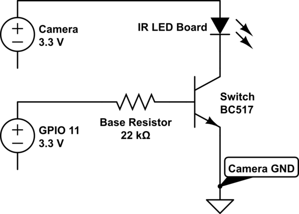
schematic

simulate this circuit – Schematic created using CircuitLab

I tried to use a BC517 transistor because of the high gain and high current. I tried various base resistors between 22k and 1k ohm. However, the LED never turned on after setting the GPIO pin to high.

Any suggestions? Like I said I'm really new to electronics, so even some tips on how to actually figure out what kind of base resistor I need would be really helpful. From what I've read online it depends on the "load resistance". There are no data sheets available for the IR boards, even the WaveShare support could not provide them. All I know is that the LEDs are 3W and that the camera outputs 3.3V. With that limited knowledge I then tried to calculate/measure the load resistance, but my results suggested using a 22k resistor which did not work.

3
  • You need to connect the Camera GND to RPi GND.
    – hcheung
    Commented Feb 13, 2018 at 23:51
  • @hcheung isn‘t that already connected through the CSI (camera) cable?
    – Alex
    Commented Feb 14, 2018 at 1:07
  • My comment was based on your diagram which is not clear whether RPi GND is connected to Camera GND
    – hcheung
    Commented Feb 14, 2018 at 9:36

2 Answers 2

2

This is much more of an electrical engineering question then a pi question. But you don't need to be using a Darlington pair transistor. You are just switching a small load, which means you are using the transistor in saturation, unlike an amplifier which is what the Darlington pair is normally used for.

1k should be fine for the base resistor, and the circuit is right (make sure the grounds are the same as in the comments) but I would switch out the transistor for a different one Look here

Also take a look at the voltage drop between collector and emitter for whatever transistor you use, because you are only working with 3.3V, if it has a drop of 0.7V the camera is probably not going to be happy.

I stole this explanation from here:

Back on Darlington voltages -

Darlington transistors do not work well in saturation. When the primary current carrying transistor is saturated, the collector voltage of the input transistor is lower than its emitter, and it no longer provides the desirable gain. In that mode, the input transistor is not much more than a diode in series with the base of the second transistor. That is one of the reasons why it is so hard to get a Darlington into genuine saturation. The current gain of the input transistor helps, nicely, until the collector voltage gets down to about 1V, give or take a little. Then, it turns into mush.

Yes, in your post just preceding. That is because of the Darlington pair, for the reason I just described. I would not describe it, however, as "taking voltage away from the device I was switching". Instead, I would say that the (effective) on-resistance simply is not very low. It does, however, provide less voltage drop across the load.

Jim

8
  • Thank you for your answer. Your link mentions the 2N3904 which I do not have, but a BC547 should be similar. But those transistors have a collector current of 0.1A. Is this enough for 3W LEDs? Also, what do you mean by „make sure the grounds are the same as in the comments“?
    – Alex
    Commented Feb 14, 2018 at 1:25
  • Update: I just went ahead and tested it, with a BC547 the switching works! But the IR LED seems to be less bright... Any suggestions?
    – Alex
    Commented Feb 14, 2018 at 1:59
  • Is there a reason you have to drive it with the 3.3v from camera? Seems having a dedicated supply would allow you to increase the voltage slightly to make up the loss at the transistor. Could use a variable regulator and a small pot so you could adjust the brightness manually or there are ways the pi could control that too
    – Chad G
    Commented Feb 14, 2018 at 4:47
  • power (W)=Voltage(V)*Current(I) So 3W=3.3V*I So they are drawing almost an amp at full power
    – Chad G
    Commented Feb 14, 2018 at 16:07
  • That's what I calculated as well and why I initially tried to use a BC517. I now switched the BC547 to a BC337 which works a little bit better (I_c = 0.8A instead of 0.1A).
    – Alex
    Commented Feb 14, 2018 at 16:18
0

FYI: I use a IRLZ34N without resistor. Works so far. GPIO is connected directly to Pin1 (left), Pin2 (middle) to LED GND and Pin3 (right) to Camera-Board GND. Very nice, because now i can control IR-Filter and IR-LED trough GPIO.

Edit: Now you can also "dimm" the LED using pigpio -> pigs p GPIO-PIN 0-255

Your Answer

By clicking “Post Your Answer”, you agree to our terms of service and acknowledge you have read our privacy policy.

Not the answer you're looking for? Browse other questions tagged or ask your own question.