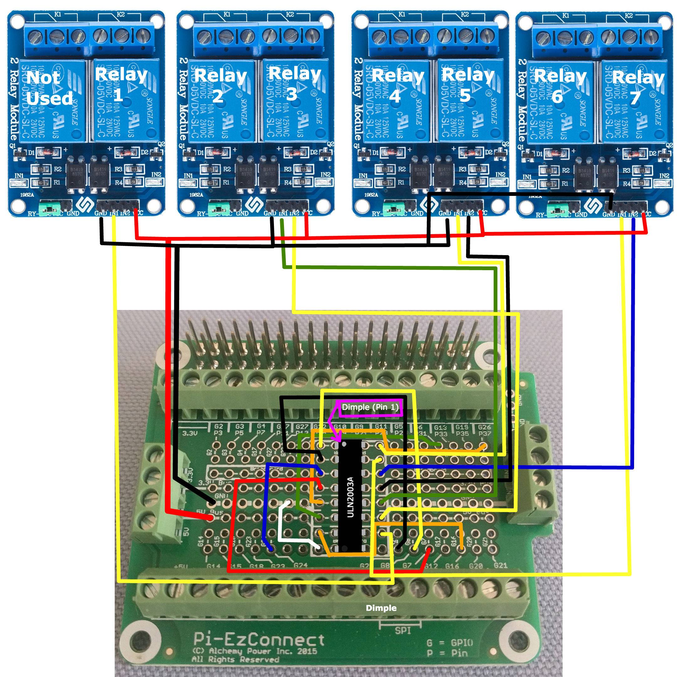
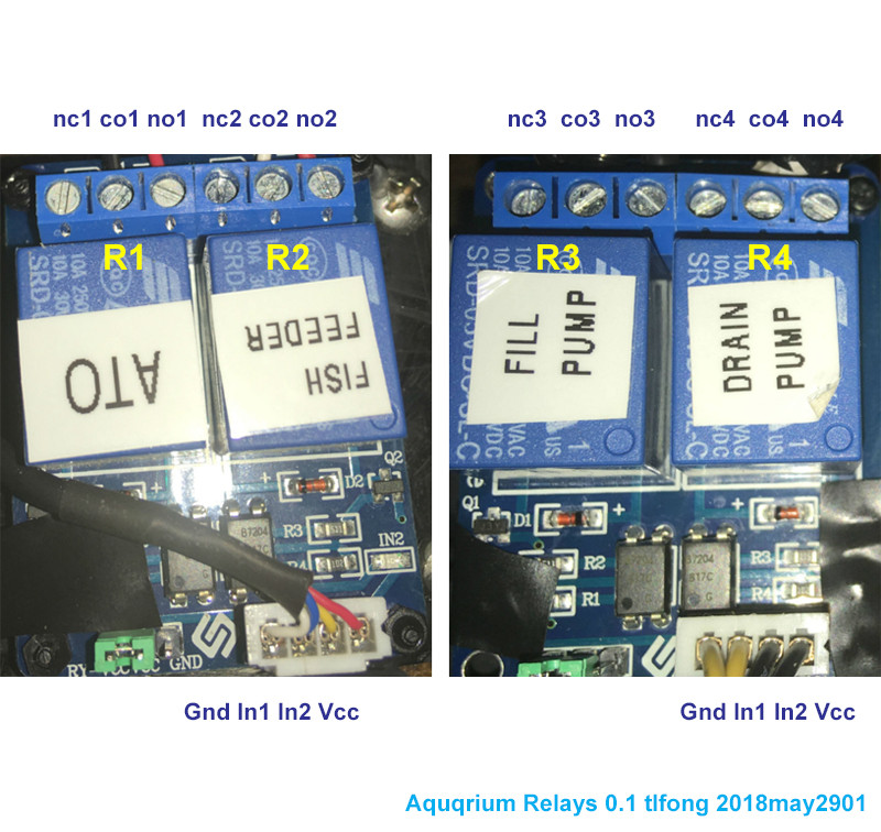
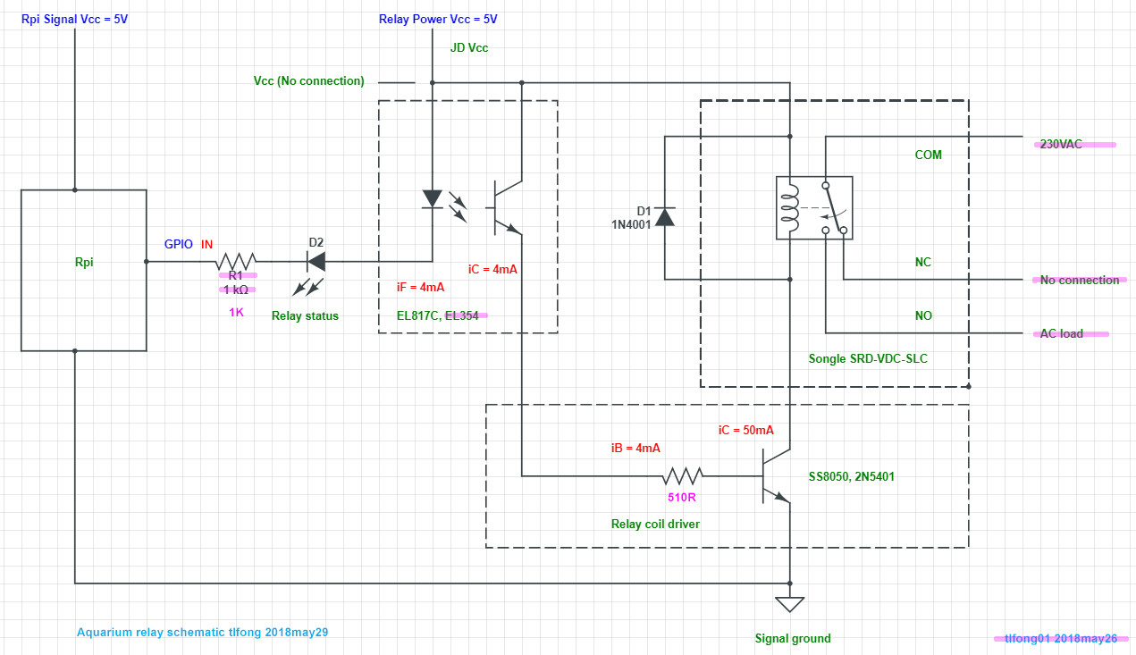
 I have 4 Sunfounder 2 channel relays 7 of which that I'm using to control some things on my aquarium. I suspect that I may have wired them up wrong somehow though. The behavior I'm seeing is as follows;
if I open either Drain Pump/Fill Pump relay
- The corresponding relay opens but if the ATO relay is open, it will close.
- Closing either Drain Pump/Fill Pump relays has no effect on the ATO relay
If I close the ATO relay
- The Fish Feeder relay opens.
- Inversely if I open the ATO relay the Fish Feeder relay closes.
Sample code for opening and closing relays called from the command line
const Gpio = require('onoff').Gpio;
const drain_relay = new Gpio(7, 'out');
const fill_relay = new Gpio(8, 'out');
const feed_relay = new Gpio(14, 'out');
const ato_relay = new Gpio(18, 'out');

drain_relay.writeSync(0) //closes the drain relay
drain_relay.writeSync(1) //opens the drain relay
Similar writeSync calls passing 0 to close or 1 to open the other relays are made.
These were just a couple of the anomalies I found. There could be more.
On my Raspberry Pi hat I connect the 4 pin GND to ground and VCC to +5V and IN1 and IN2 to GPIO pins. Could the signal be jumping pins on the hat? Or is there something else I'm missing?
UPDATE 6/6/18
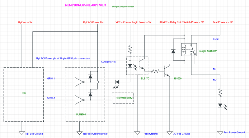
I followed some direction that I received on the Raspberry Pi Forum here. The instruction I got was to add a ULN2003A Darlington transistor between gpio OUT and relay IN. I added this in between as instructed there. But now all relay LEDs stay on. When I command the relay open or closed the LED changes from bright to dim or dim to bright with no relay click indicating the relay itself had changed.
Update 6/8/18 8:54am EDT
Just checked voltage output between Gnd to IN1 and Gnd to IN2 pins on relay board having relays 4 and 5 at the four pin connector with the relay disconnected. Voltages were as follows;
note: open and closed states are assumed because my relays aren't connected and haven't been actuated since adding the Darlington.
Relay | State | PIN | Voltage
 4    post boot  IN1     600mv
 4       Open    IN1     1.7mv
 4      closed   IN1     900mv
 5    post boot  IN2     600mv(Reset to 1.7mv post Relay 4 actuation)
 5       Open    IN2     1.7mv
 5      closed   IN2     900mv
Questions
- Shouldn't I be seeing 5V when relays are closed?
- If I understand correctly the relays should be closing when voltage goes to zero. Is 1.7V enough to keep the relay LED lit and prevent the relay from closing?
- Do these seem like voltage numbers I should be expecting to see given my hardware and inputs?
Update 6/8/18 6:22pm EDT
I took the two hats off my Pi and started going through my wires looking for a loose connection or something. I found a 5v wire on my new hat that, while the solder joint looked good, the wire seemed to move pretty freely compared to the others near the solder joint.
While I was there fixing that I knew I had left a couple of the 5v and ground wires that went to the 4 pin connectors on the relay boards on my original hat when I moved the ULN2003A , the GPIO signal wires and the ULN2003A OUT to relay IN wires to the new hat. I decided to bring those 5v and ground wires over to the new hat as well. This way I have all my relay related connections on one hat and sensor related connections on the other.
After putting everything back together the relay lights no longer lit up on boot. Good!?! Maybe? My relays still weren't actuating with my commands. And now there are no changes to the LED lights. they just stay off.
I disconnected the 4 pin connectors from the relay boards and began checking them with the volt meter. I no longer had 5V across any of the VCC GND pins. But when I probed GND to IN pins and toggled the associated GPIO I still got a voltage reading between zero and 900mv.


