1

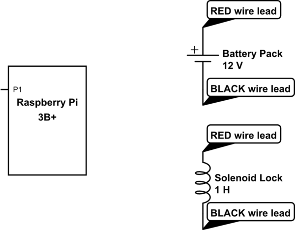
I'm new to this, and I can't see how to control a solenoid lock using raspberry (The wirings). I have an 8x AA Battery pack which is wired to output 12V. I don't know where to connect the black and red wire of solenoid lock, or the black and red wire of battery component. Wish you could help a newbie.

I have the following: - RPi 3B+ - Battery pack with red and black wire - Solenoid lock 12v dc with red and black wire.

schematic

simulate this circuit – Schematic created using CircuitLab

1
  • Basically you can't (without additional circuitry) DO NOT try without - you will destroy your Pi. I doubt it is even feasible with AA batteries, but you need to provide more detail.
    – Milliways
    Commented Jan 3, 2019 at 7:32

2 Answers 2

2

Assuming you have a lock such as this one, it will be in locked position, when not connected to power. On the other hand, if you supply 12V to your cables the solenoid will pull the piston in.

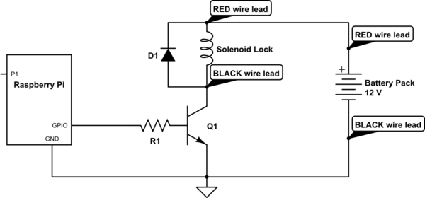
In order to operate such a device from a microcontroller, you need additional components, such as a power transistor (with heat sink) to control the power supply to the lock, a diode, resistors, as mentioned in the description of above link.

Here is the respective wiring diagram for the linked product. On the Raspberry Pi side you need to connect a digital out GPIO pin to control the power transistor (in the diagram an Arduino is used as example instead of an Raspberry Pi). With the voltage of the GPIO which is connected to the gate of the transistor you can control if current is flowing through the transistor and thus also if you pull in the piston or not.

However, please check also the documentation of the lock you bought, as the specification might be different to the device linked.
2

To expand on @oh.dae.su's answer, here's a schematic that shows in general how you could connect the components you've described in your question. If you'd care to supply the specifications for your solenoid lock, we'll update the schematic to show some specific components and component values that will make your circuit work properly.

schematic

simulate this circuit – Schematic created using CircuitLab

Your Answer

By clicking “Post Your Answer”, you agree to our terms of service and acknowledge you have read our privacy policy.

Not the answer you're looking for? Browse other questions tagged or ask your own question.