1

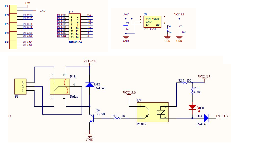
I am trying to drive the 12V/24V relay using Rasberry pi 3. I have got schematic from one of the forum.I have question related to below schmatic.

1) The ckt build to drive 5V relay . How can use below Ckt to drive 12V/24V relay 2)how to select the value of resistance in below case.

Rasberry pi-3

Image

2
  • Can you give us the web link of (1) your 12V/24V relay module, (2) the 3V3/5V relay switch driving circuit?
    – tlfong01
    Commented Jun 11, 2019 at 10:05
  • What's a ckt? A misspelled "circuit"? And which resistance are you referring to, R19? Commented Jun 11, 2019 at 12:03

2 Answers 2

0

The circuit you included would, in principle, work with any relay, provided a suitable transistor is used.

There are some issues; what is D14 supposed to do (apart from dropping voltage, making it harder to turn on the opto-isolator).

The use of an opto-isolator adds no value (unless you need galvanic isolation), the limited current transfer ratio just makes it harder to saturate the transistor.

You would be better just to drive the relay with a transistor see https://elinux.org/RPi_GPIO_Interface_Circuits#Driving_a_relay

The resistor R19 is (transistor Hfe) * Vcc / (relay current) (assuming the current transfer ratio is sufficiently high to actually drive the circuit).

2
  • Thanks for all your suggestion.I have raised this question because I have seen lot of sheild with Relay module integrated with Rasberry pi. Usually they use above CKTs . I have attached the CKt where they driving 5V relay. Some people uses UL2003 also where they do isolation .It has clear my doubt.
    – Ajit N
    Commented Jun 12, 2019 at 3:25
  • @AjitN There are lots of cheap Chinese modules, "designed" for Arduino. They do work on Arduino, but not Pi, but are poor design. If the output circuit shares ANY connection with the input (Gnd or Vcc) the opto-isolator provides no additional isolation over that the relay does. (I have designed lots of circuitry using opto-isolators where I needed isolation.)
    – Milliways
    Commented Jun 12, 2019 at 3:45
1

I think the circuit you've illustrated is more complex than what is needed for simply driving a 12/24V relay. The primary considerations in using GPIO to control external devices are:

  1. GPIO has low output voltage (3.3 volts),

  2. GPIO has low drive current

  3. GPIO is fragile in the sense that it will not tolerate over-voltage

I feel the optimal device for interfacing GPIO to external devices is the Darlington Transistor (aka Darlington pair). For your application, I'd suggest you consider a device with characteristics like the 2N6387.

With respect to the 3 considerations above, this Darlington transistor will:

  1. "Turn on" (saturate) at a voltage of approx 0.7 volts (at Ic=2.0 A), easily in the range of the GPIO

  2. Has a dc current gain (hFE) of approximately 3,000, thereby requiring a miniscule drive current, again, easily within the capability of the GPIO

  3. Will isolate the GPIO from the 12/24 V relay voltage.

The schematic below may serve as a starting point and illustrate the simplicity of interfacing a Darlington transistor with the GPIO:
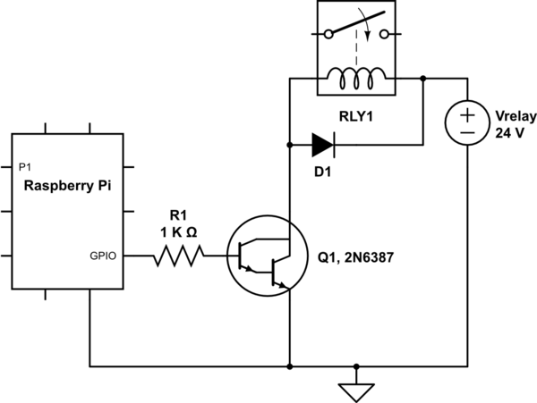
schematic

simulate this circuit – Schematic created using CircuitLab

The diode D1 will serve to limit the inductive "kick" generated when the Darlington transistor is turned "OFF". The resistor R1 will limit the base current being sourced to the Darlington; sized here for approx 2 mA. There are a few other embellishments that could be made, but this will serve as a reasonable starting point. If you have questions, let us know.

Your Answer

By clicking “Post Your Answer”, you agree to our terms of service and acknowledge you have read our privacy policy.

Not the answer you're looking for? Browse other questions tagged or ask your own question.