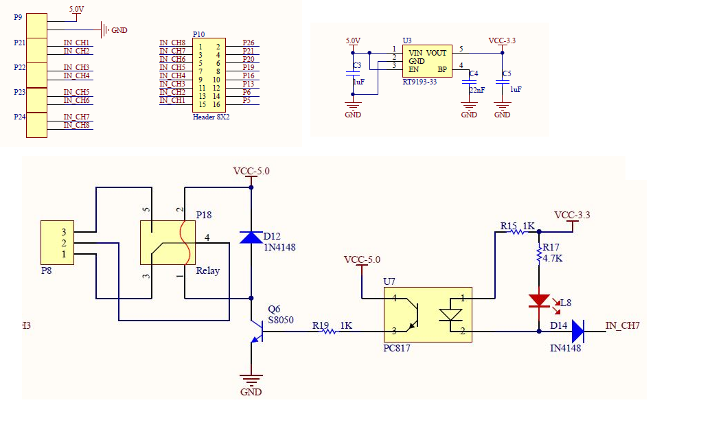
I think the circuit you've illustrated is more complex than what is needed for simply driving a 12/24V relay. The primary considerations in using GPIO to control external devices are:
GPIO has low output voltage (3.3 volts),
GPIO has low drive current
GPIO is fragile in the sense that it will not tolerate over-voltage
I feel the optimal device for interfacing GPIO to external devices is the Darlington Transistor (aka Darlington pair). For your application, I'd suggest you consider a device with characteristics like the 2N6387.
With respect to the 3 considerations above, this Darlington transistor will:
"Turn on" (saturate) at a voltage of approx 0.7 volts (at Ic=2.0 A), easily in the range of the GPIO
Has a dc current gain (hFE) of approximately 3,000, thereby requiring a miniscule drive current, again, easily within the capability of the GPIO
Will isolate the GPIO from the 12/24 V relay voltage.
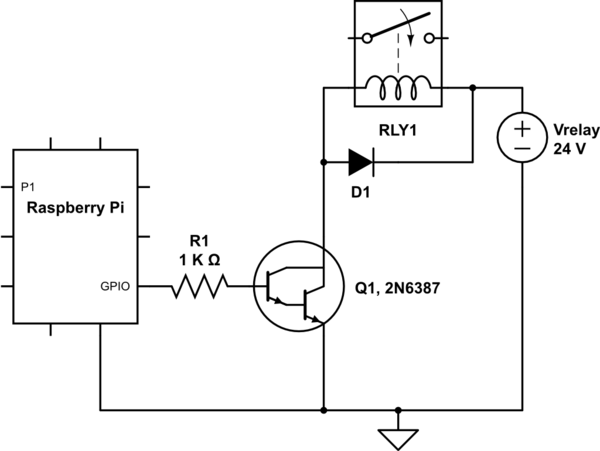
The schematic below may serve as a starting point and illustrate the simplicity of interfacing a Darlington transistor with the GPIO:

simulate this circuit – Schematic created using CircuitLab
The diode D1 will serve to limit the inductive "kick" generated when the Darlington transistor is turned "OFF". The resistor R1 will limit the base current being sourced to the Darlington; sized here for approx 2 mA. There are a few other embellishments that could be made, but this will serve as a reasonable starting point. If you have questions, let us know.


ckt? A misspelled "circuit"? And which resistance are you referring to, R19?