Question
How can PicoW read MEMS digital microphone output?
Answer
Update 2023jan09hkt1103
0.6 Microphone not working because input frequency to low, < 1MHz
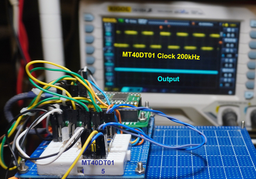
Earlier I used 200kHz as clock frequency but found nothing happening. I checked the datasheet and found that the minimum frequency is 1 MHz (Max 3.5MHz). Now I have a problem, because it seems that the PicoW's system timers are software timers and so could not support too many clocks at high frequency higher than 500 KHz. So now I need to check if an external clock > 1MHz can solve the problem.
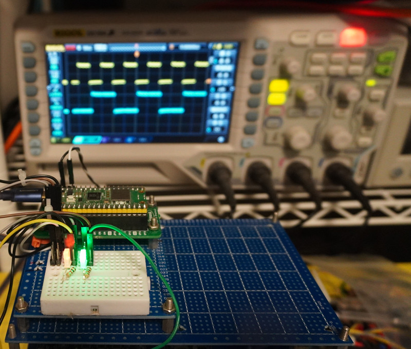
0.5 Real time test setup
mt40dt01 test program listing - https://penzu.com/p/2f213cb6
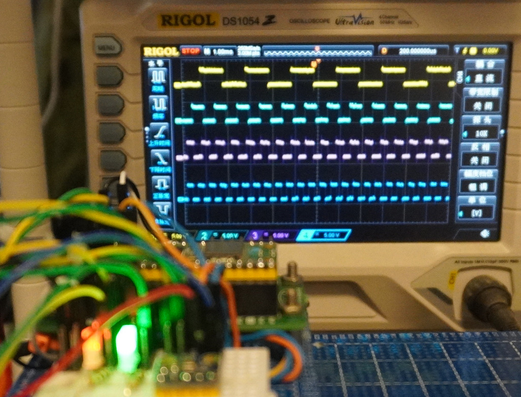
0.4 Creating 4 PicoW system clocks, two for real time tone signals, two for MT34DT01 MEMS digital microphone clock inputs
PicoW Mems Digi Mic v13.0 Program Listing
# PicoW Mems Digi Mic v16.0 - tlfong01 2023jan07hkt2138

import machine
import utime
from machine import Pin, Timer, RTC

print('MemsDigiMicV16.0, 2023jan07hkt2138')

redFreq     = 20000  # DigiMic #1 Clock signal
grnFreq     = 4      # For troubleshooting

redLed      = Pin(0, Pin.OUT, value = 1) # Create Red LED object, init On
grnLed      = Pin(1, Pin.OUT, value = 1) # Create grn LED object, init On

redTimer    = Timer() # Red LED timer, callback toggleRedLed
grnTimer    = Timer() # Grn LED timer, callback toggleGrnLed

def toggleRedLed(dummy): #ISR RedLed
    redLed.toggle()
    return

def togglegrnLed(dummy): #ISR grnLed
    grnLed.toggle()
    return

redTimer.init(freq = redFreq, mode = Timer.PERIODIC, callback = toggleRedLed)
grnTimer.init(freq = grnFreq, mode = Timer.PERIODIC, callback = togglegrnLed)

utime.sleep(10)
redTimer.deinit()
grnTimer.deinit()
redLed.off()
grnLed.off()

# *** End of program ***
0.3 Using MT34DT01 MEMS Digital Microphone for Very simple Speech Recognition
The MP34DT01-M MEMS digital microphone datashheet says it can be used for AI applications such as speech recognition, (Ref 1). Now I am thinking of exploring the fisibility of doing very simple speech recognition, say, for a very, very small subset of audio signals, denoting doggie commands like "Sit", "Eat", "OK" etc.
I read that it is practical to use Rpi python to do Alphabet reqognition of 26 handwritten patterns A to Z, using CNN (Convolutional Neural Network), for example, Glezer, Ref 2. In CNN application usually represent one visual paatern, say one alphabet, by a liner list of bits. For audio patterns, I think we can also similarly represent doggie commends "Sit", "Eat" etc, each by a list of bits.
The MEMS digital microphone MP34DT01 seems ideal for our simple application. This is what will explored in the subsquent sections.
(1) MP34DT01-M MEMS audio sensor omnidirectional digital microphone - STM 2014
(2) Running a Convolutional Neural Network on Raspberry PI - Marcelo Glezer, 2020oct01
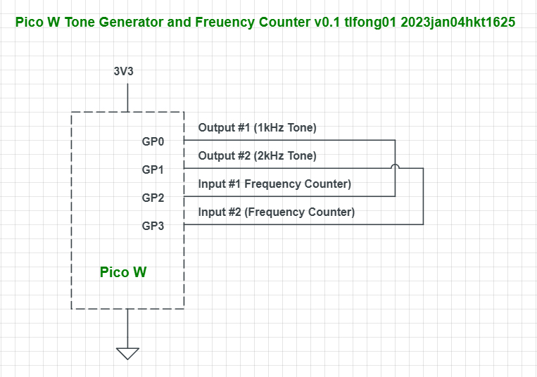
0.2 Tone Generator and Frequency Counter Schematic
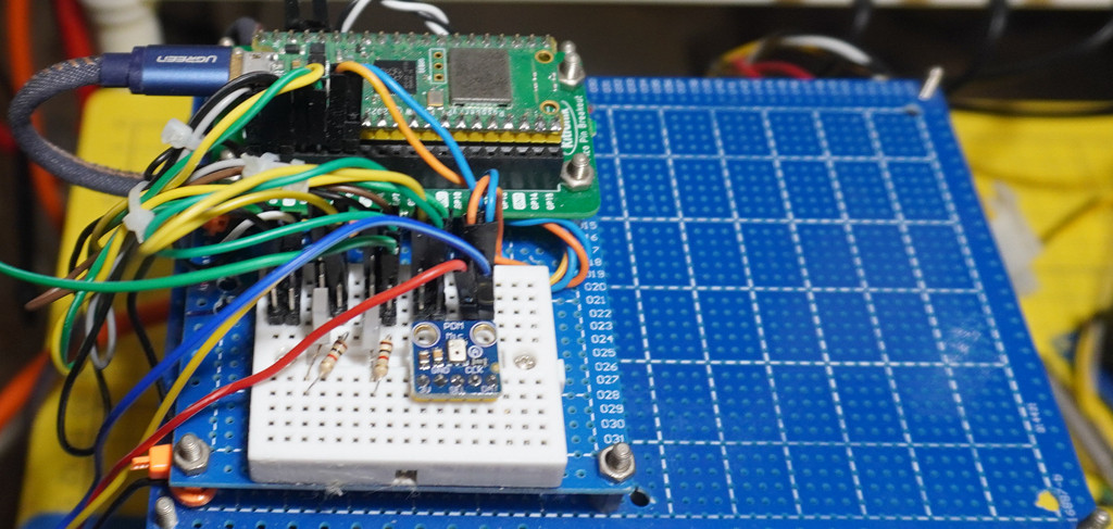
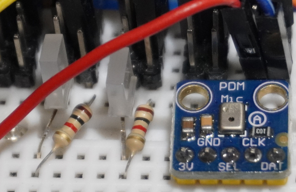
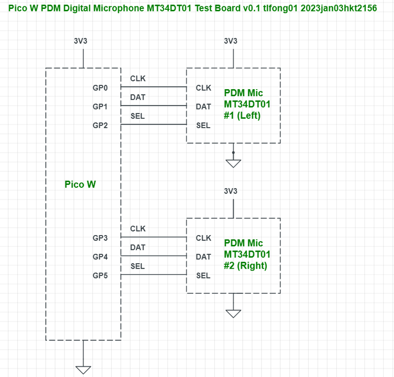
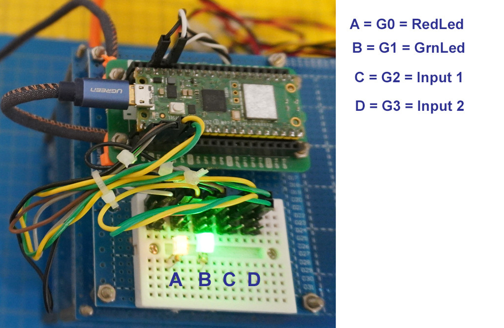
0.1 MEMS PDM Digital Microphone MT34DT01 Test Setup V0.1
1. Introduction.
We can connect the MEMS microphone output pin to a PicoW GPIO pin and read signal, into a list for later processing.
2. Simulation
For prototyping, we can simulate the microphone output signal as a GPIO output pin connected blinking LED, and use another GPIO input pin to read the blinking LED pin.
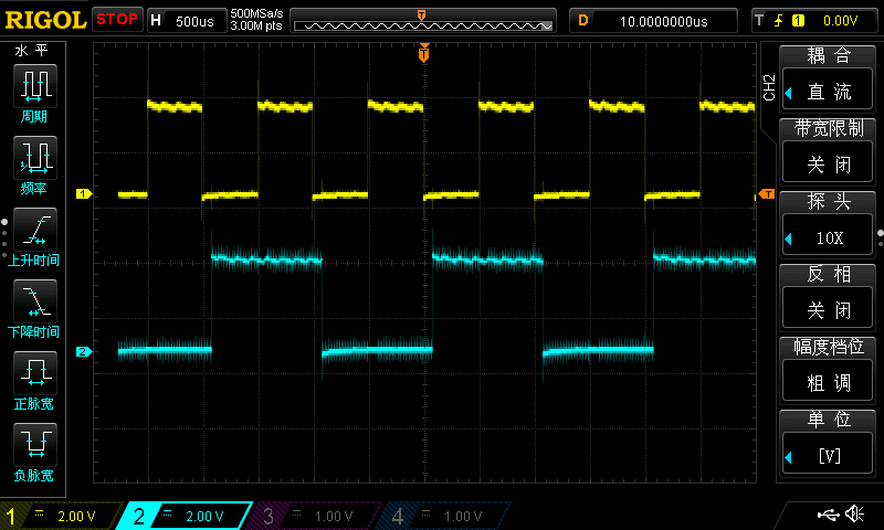
3. Trying Blink rates 1kHz, 2kHx, to simulate 1kHz, 2kHz tones
*4. The OP wishes to connect the MEMS digital mic output to PicoW. So now I am looking at the real thing.
5. MP34DT01-M MEMS audio sensor omnidirectional digital microphone
(5.1) MP34DT01-M MEMS audio sensor omnidirectional digital microphone - ST
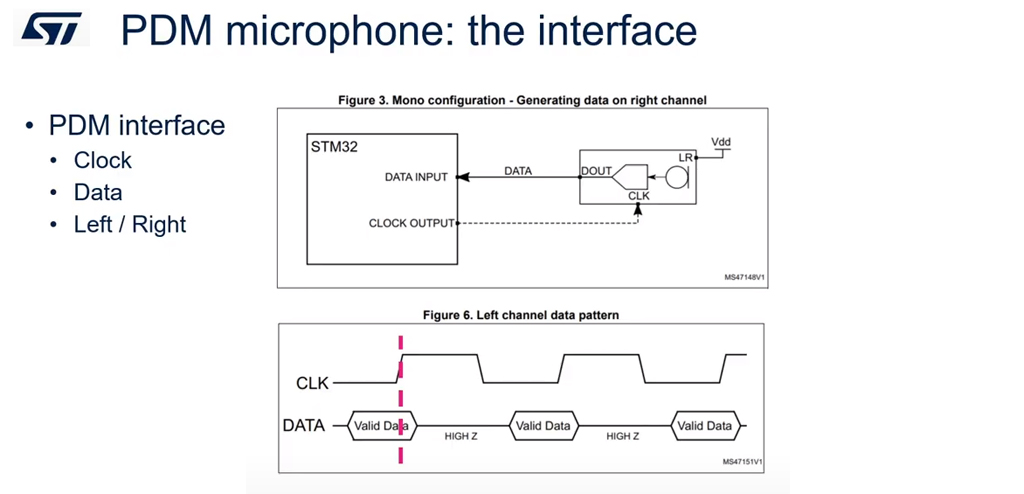
(5.2) PDM Microphont: PDM Signal Definition - ST Video
6. MT34DT01 MEMS Digital Microphone
9. / to continue, ...
References
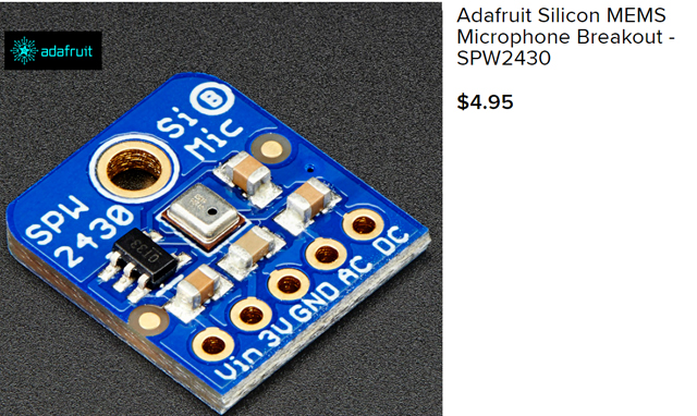
(1) Adafruit PDM Microphone Breakout 1
(2) Adafruit PDM Microphone Breakout 2
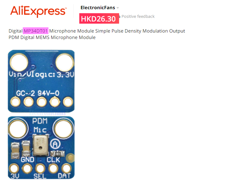
(4) TaoBao MP34DT01 MEMS PDM Microphone - ¥25
(5) 1000 Hz Test Tone - Sonic Electronix
(6) Using a Digital Microphone (MT34DT01) on STM32 - Dario Petrillo, Hackster, 2022jul14
Appendices
Appendix A - MicroPython program blinking two LEDs simulating two MEMS digital microphone output signals
# Pico W Blink Two LEDs - tlfong01 2023jan01hkt1941

# *** Modules ***
import machine
from machine import Pin, Timer

# *** Configuration***
redLed      = Pin(0, Pin.OUT)
greenLed    = Pin(1, Pin.OUT)

redFreq     = 2
greenFreq   = 4

redTimer    = Timer()
greenTimer  = Timer()

# *** Callbacks ***
def blinkRedLed(dummy):
    redLed.toggle()
    return

def blinkGreenLed(dummy):
    greenLed.toggle()
    return

# *** Main ***
redTimer.init(freq = redFreq, mode = Timer.PERIODIC, callback = blinkRedLed)
greenTimer.init(freq = greenFreq, mode = Timer.PERIODIC, callback = blinkGreenLed)

# *** End of program ***
Appendix B - Blinking LEDs Video
Appendix C - MEMS Mic, PicoW GPIO Eval Brd Setup
# PicoW GPIO Input Testing v7.0 - tlfong01 2023jan02hkt1410

# *** 1.0 Modules ***
import machine
import utime
from machine import Pin, Timer

# *** 2.0 Configuration and Functions ***

# 2.1 Blinking LED Configurations and Functions
redFreq     = 6 # Red LED blinking frequency
greenFreq   = 3 # Green LED blinking frequency

redLed      = Pin(0, Pin.OUT, value = 1) # Create Red LED object, init On
greenLed    = Pin(1, Pin.OUT, value = 1) # Create Green LED object, init On

redTimer    = Timer() # Red LED timer, callback blinkRedLed
greenTimer  = Timer() # Greed LED timer, callback blinkGreenLed

# 2.2 Blinking LED Callbacks
def blinkRedLed(dummy):
    redLed.toggle()
    return

def blinkGreenLed(dummy):
    greenLed.toggle()
    return

# *** 3.0 GPIO Input Configurations and Functions ***

readGpioPin2 = Pin(2, Pin.IN, Pin.PULL_UP) # Create GPIO input pin object
readGpioPin3 = Pin(3, Pin.IN, Pin.PULL_UP) # Create GPIO input pin object

def readRedLed():
    ledStatus = readGpioPin2()
    if ledStatus == 1:
        return "High"
    else:
        return "Low"

def readGreenLed():
    ledStatus = readGpioPin3()
    if ledStatus == 1:
        return "High"
    else:

        return "Low"

def readPrintRedGreenLedStatus():
    redLedStatus = readRedLed()
    greenLedStatus = readGreenLed()
    print('RedLedStatus   =', redLedStatus)
    print('GreenLedStatus =', greenLedStatus)
    return

### *** 4.0 / to continue, ... ***

# *** 9.0 Main ***

# 9.1 Run Red/Green Timer for 2 seconds

redTimer.init(freq = redFreq, mode = Timer.PERIODIC, callback = blinkRedLed)
greenTimer.init(freq = greenFreq, mode = Timer.PERIODIC, callback = blinkGreenLed)
utime.sleep(2)
redTimer.deinit()
greenTimer.deinit()

# 9.2 Set/Read/Print Red/Green LED status

redLed.on()
greenLed.on()

readPrintRedGreenLedStatus()

# *** End of program ***

