Question
How can PicoW read MEMS digital microphone output?
Answer
Introduction
1. Overview.
We can connect the MEMS microphone output pin to a PicoW GPIO pin and read signal, into a list for later processing.
2. Simulation
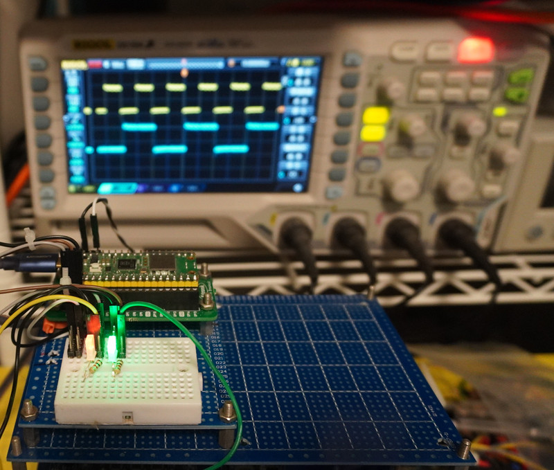
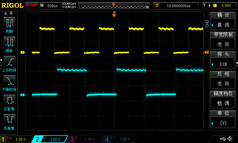
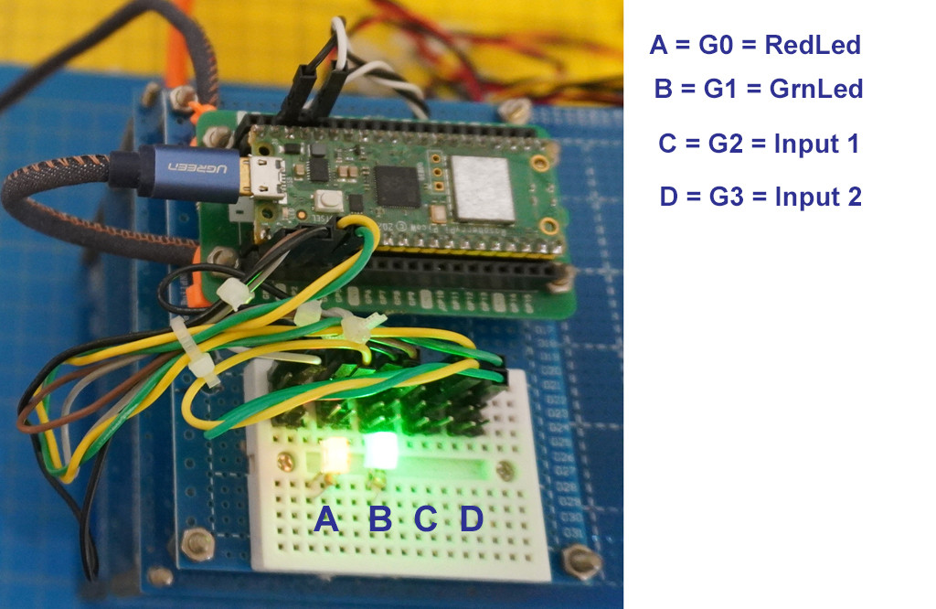
For prototyping, we can simulate the microphone output signal as a GPIO output pin connected blinking LED, and use another GPIO input pin to read the blinking LED pin.
3. Trying Blink rates 1kHz, 2kHx, to simulate 1kHz, 2kHz tones
4. / to continue, ...
References
(1) Adafruit PDM Microphone Breakout 1
(2) Adafruit PDM Microphone Breakout 2
(4) TaoBao MP34DT01 MEMS PDM Microphone - ¥25
(5) 1000 Hz Test Tone - Sonic Electronix
Appendices
Appendix A - MicroPython program blinking two LEDs simulating two MEMS digital microphone output signals
# Pico W Blink Two LEDs - tlfong01 2023jan01hkt1941

# *** Modules ***
import machine
from machine import Pin, Timer

# *** Configuration***
redLed      = Pin(0, Pin.OUT)
greenLed    = Pin(1, Pin.OUT)

redFreq     = 2
greenFreq   = 4

redTimer    = Timer()
greenTimer  = Timer()

# *** Callbacks ***
def blinkRedLed(dummy):
    redLed.toggle()
    return

def blinkGreenLed(dummy):
    greenLed.toggle()
    return

# *** Main ***
redTimer.init(freq = redFreq, mode = Timer.PERIODIC, callback = blinkRedLed)
greenTimer.init(freq = greenFreq, mode = Timer.PERIODIC, callback = blinkGreenLed)

# *** End of program ***
Appendix B - Blinking LEDs Video
Appendix C - MEMS Mic, PicoW GPIO Eval Brd Setup
# PicoW GPIO Input Testing v7.0 - tlfong01 2023jan02hkt1410

# *** 1.0 Modules ***
import machine
import utime
from machine import Pin, Timer

# *** 2.0 Configuration and Functions ***

# 2.1 Blinking LED Configurations and Functions
redFreq     = 6 # Red LED blinking frequency
greenFreq   = 3 # Green LED blinking frequency

redLed      = Pin(0, Pin.OUT, value = 1) # Create Red LED object, init On
greenLed    = Pin(1, Pin.OUT, value = 1) # Create Green LED object, init On

redTimer    = Timer() # Red LED timer, callback blinkRedLed
greenTimer  = Timer() # Greed LED timer, callback blinkGreenLed

# 2.2 Blinking LED Callbacks
def blinkRedLed(dummy):
    redLed.toggle()
    return

def blinkGreenLed(dummy):
    greenLed.toggle()
    return

# *** 3.0 GPIO Input Configurations and Functions ***

readGpioPin2 = Pin(2, Pin.IN, Pin.PULL_UP) # Create GPIO input pin object
readGpioPin3 = Pin(3, Pin.IN, Pin.PULL_UP) # Create GPIO input pin object

def readRedLed():
    ledStatus = readGpioPin2()
    if ledStatus == 1:
        return "High"
    else:
        return "Low"

def readGreenLed():
    ledStatus = readGpioPin3()
    if ledStatus == 1:
        return "High"
    else:

        return "Low"

def readPrintRedGreenLedStatus():
    redLedStatus = readRedLed()
    greenLedStatus = readGreenLed()
    print('RedLedStatus   =', redLedStatus)
    print('GreenLedStatus =', greenLedStatus)
    return

### *** 4.0 / to continue, ... ***

# *** 9.0 Main ***

# 9.1 Run Red/Green Timer for 2 seconds

redTimer.init(freq = redFreq, mode = Timer.PERIODIC, callback = blinkRedLed)
greenTimer.init(freq = greenFreq, mode = Timer.PERIODIC, callback = blinkGreenLed)
utime.sleep(2)
redTimer.deinit()
greenTimer.deinit()

# 9.2 Set/Read/Print Red/Green LED status

redLed.on()
greenLed.on()

readPrintRedGreenLedStatus()

# *** End of program ***


