6

I have a simple circuit that runs on 5 volts. Let's just say for simplicity that it is a circuit with an LED that lights up when a push button is pressed. The problem is that it has a push button switch in it, but I need to control turning on and off the circuit from a Raspberry Pi GPIO pin instead of the push button.

How can I do this?

Edit: I guess the answer is a MOSFET.

3
  • 4
    There are a million examples on this site, and the web. As a start try searching for "Microcontroller Mosfet switch"
    – Tyler
    Commented Jan 15, 2016 at 19:51
  • What about a simple relay?
    – fcm
    Commented Jan 16, 2016 at 5:57
  • Same issue here. Just posted a Q about a specific MOSFET that I think can be used. Answers and comments would be very much appreciated: raspberrypi.stackexchange.com/questions/72884/…
    – SDsolar
    Commented Sep 23, 2017 at 21:18

2 Answers 2

8

Adding to the answer above, how to do this really depends on the load you want to switch.

Here's a post about how much current you can draw from the GPIO see here

A few cases:

1) You have only one LED, that's it, and 20mA or so will do. See here an internet article on how to do this with one resistorsee here

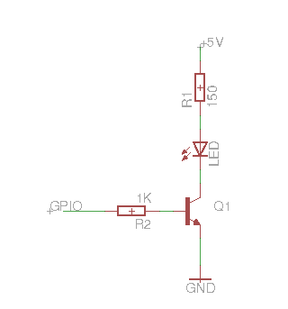
2) You have more than one LED, you want the LED to shine brighty or you have something else that can work with 5V but draws more than say 20 mA. Then use a transistor (BJT or FET) as below:

enter image description here

3) You want to switch a heavy DC load, or you want to switch an AC load, then the recommendation above with a relay is a good choice.

If you can be more precise what you want to switch, then just ask.

2

Try this:

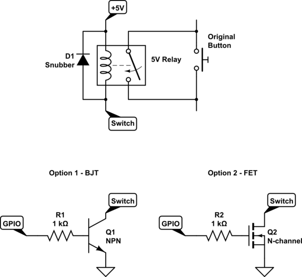
schematic

simulate this circuit – Schematic created using CircuitLab

Use either Option 1 or Option 2, depending on what parts you can find and what you're comfortable with. In either case, the Switch label on the transistor circuit connects to the Switch label on the relay circuit, so that the transistor is simply an amplifier to activate the relay. The functional difference is that the BJT needs a small continuous current to hold it on while the FET requires a spike in current to change state and then sits nicely without drawing anything. But since you're only going to blink it anyway, even that hardly matters.

Even though the FET doesn't draw any control current just sitting on, I'd keep R2 anyway to control the switching spike and avoid stressing the Pi's output driver. For either option, choose the resistance as if the transistor were a short-circuit.

Also don't forget D1. It limits the voltage spike when the relay turns off to a diode drop above +5V, so the transistor only has to handle that instead of theoretically infinite. (lower in practice, but easily 100V or more)

3
  • The relay is the most generic case (provided it's contacts are adequately rated and suited to the circuit the switch is in - some materials need a certain amount of current to be passed through them otherwise they degrade - I tried to find a Wikipedia link but that detail is absent from the Relay entry. 8-( ) - The other two "Option 1 - BJT" and "Option 2 - FET" will only work correctly as drawn if the existing switch is wired with one side to ground (and the other at a positive D.C. Voltage with respect to that level)...!
    – SlySven
    Commented Jan 16, 2016 at 12:31
  • @SlySven I probably should have been more clear to start with, so I edited my answer accordingly, but both transistor options are intended to power the relay, not to stand alone as their own solutions. Though like you said, they could work on their own as long as the circuit being controlled is configured accordingly.
    – AaronD
    Commented Jan 16, 2016 at 21:22
  • Ah, that makes more sense. The only other proviso that users need to be aware of is that some GPIO pins default to being pulled high before the RPi has completely finished booting up. I think that some editing of the configuration file config.txt (?) may affect this - but the user should, ideally, check how each line and thus the relay behaves during boot-up before connected any significant load (for, say, a Mains Power application) to the contacts of the relay! 8-/
    – SlySven
    Commented Jan 17, 2016 at 17:55

Your Answer

By clicking “Post Your Answer”, you agree to our terms of service and acknowledge you have read our privacy policy.

Not the answer you're looking for? Browse other questions tagged or ask your own question.