replaced http://raspberrypi.stackexchange.com/ with https://raspberrypi.stackexchange.com/
Source Link

I am building a simple resistor / capacitor in series (RC) circuit to measure resistance with my Raspberry Pi A+.

RC Design
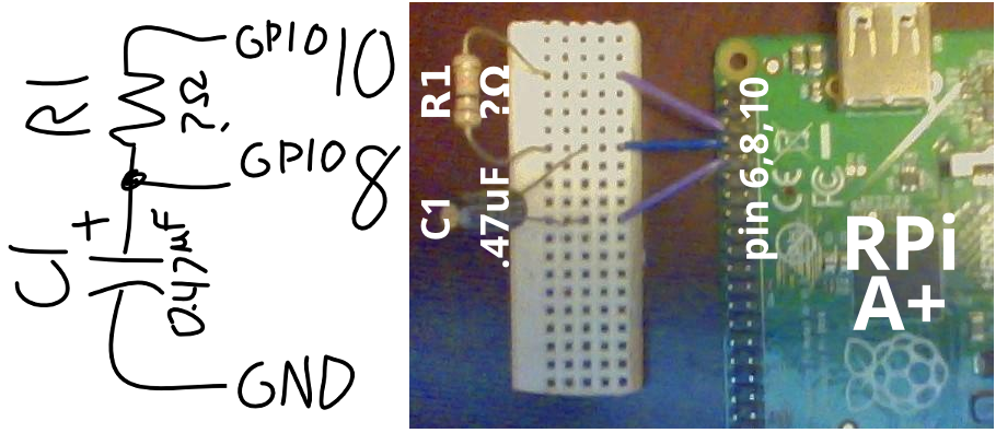
Enter image description here

This design is similar to the one used in this tutorial as suggested in this postthis post.

This circuit works by measuring the resistance of R1 by measuring the time required to charge C1. I do understand that Python is not a great language for precision timing, but this doesn't need to be very precise. It's mostly a project to learn circuit analysis with the Raspberry Pi. My Python script I am using for this math is the following:

# Time how long it takes for C1 to charge through R1
GPIO.setup (8, GPIO.IN);GPIO.output (10, 1)
start = time.time ()
while GPIO.input (8) == 0: False
end = time.time ()

# Divide duration by capacitance to get resistance
capacitance = 0.47 * 0.000001 # 0.47 µF
duration = end - start
resistance = duration / capacitance

resistance *= 1.85938    # <===== THE HORRIBLE MYSTERY COEFFICIENT

print ('resistance =', round (resistance), 'ohms')


Math Error - Mystery Coeficcient

The above setup outputs (mostly) accurate numbers for the value of R1. The problem is the unexplained coefficient ~1.85938. Some possible error sources I've considered include:

  • Internal resistance from the GPIO itself (with the 3.3 V, 16 mA max output per pin),
  • Problems due to inaccuracies in my components themselves (the resistors have tolerances of 5%),
  • A flaw in the universe of the kind that make 1 = 2 and never-ending chocolate possible,
  • or some combination of the above.

Why would RC circuits built with the GPIO be off by a factor of ~1.85938?

I am building a simple resistor / capacitor in series (RC) circuit to measure resistance with my Raspberry Pi A+.

RC Design

Enter image description here

This design is similar to the one used in this tutorial as suggested in this post.

This circuit works by measuring the resistance of R1 by measuring the time required to charge C1. I do understand that Python is not a great language for precision timing, but this doesn't need to be very precise. It's mostly a project to learn circuit analysis with the Raspberry Pi. My Python script I am using for this math is the following:

# Time how long it takes for C1 to charge through R1
GPIO.setup (8, GPIO.IN);GPIO.output (10, 1)
start = time.time ()
while GPIO.input (8) == 0: False
end = time.time ()

# Divide duration by capacitance to get resistance
capacitance = 0.47 * 0.000001 # 0.47 µF
duration = end - start
resistance = duration / capacitance

resistance *= 1.85938    # <===== THE HORRIBLE MYSTERY COEFFICIENT

print ('resistance =', round (resistance), 'ohms')


Math Error - Mystery Coeficcient

The above setup outputs (mostly) accurate numbers for the value of R1. The problem is the unexplained coefficient ~1.85938. Some possible error sources I've considered include:

  • Internal resistance from the GPIO itself (with the 3.3 V, 16 mA max output per pin),
  • Problems due to inaccuracies in my components themselves (the resistors have tolerances of 5%),
  • A flaw in the universe of the kind that make 1 = 2 and never-ending chocolate possible,
  • or some combination of the above.

Why would RC circuits built with the GPIO be off by a factor of ~1.85938?

Copy edited.
Source Link

what What is the resistance of the GPIO outputs?

I am building a simple resistor / capacitor in series (RC) circuit to measure resistance with my RPiRaspberry Pi A+.

RC Design

enter image description hereEnter image description here

This design is similar to the one used in this tutorial as suggest onsuggested in this post. 

This circuit works by measuring the resistance of R1 by measuring the time required to charge C1. I do understand that Python is not a great language for precision timing, but this doesn't need to be very precise. It's mostly a project to learn circuit analysis with the Raspberry Pi. My Python script I am using for this math is the following:

# timeTime how long it takes for C1 to charge thruthrough R1
GPIO.setup (8, GPIO.IN);GPIO.output (10, 1)
start = time.time ()
while GPIO.input (8) == 0: False
end = time.time ()

# divideDivide duration by capacitance to get resistance
capacitance = 0.47 * 0.000001 # 0.47 uFµF
duration = end - start
resistance = duration / capacitance

resistance *= 1.85938    # <===== THE HORRIBLE MYSTERY COEFFICIENT

print ('resistance =', round (resistance), 'ohms')


Math Error - Mystery Coeficcient

The above setup outputs (mostly) accurate numbers for the value of R1. The problem is the unexplained coefficient ~1.85938. Some possible error sources I've considered include:

  • internalInternal resistance from the GPIO itself (with the 3.3V3 V, 16mA16 mA max output per pin),
  • problemsProblems due to inaccuracies in my components themselves (the resistors have tolerances of 5%),
  • aA flaw in the universe of the kind that make 1 = 2 and never-ending chocolate possible,
  • or some combination of the above.

Does any circuit analysis / Raspberry Pi expert whyWhy would RC circuits built with the GPIO would be off by a factor of ~1.85938~1.85938?

what is resistance of the GPIO outputs

I am building a simple resistor / capacitor in series (RC) circuit to measure resistance with my RPi A+.

RC Design

enter image description here

This design is similar to the one used in this tutorial as suggest on this post. This circuit works by measuring the resistance of R1 by measuring the time required to charge C1. I do understand that Python is not a great language for precision timing, but this doesn't need to be very precise. It's mostly a project to learn circuit analysis with the Raspberry Pi. My Python script I am using for this math is the following:

# time how long it takes for C1 to charge thru R1
GPIO.setup (8, GPIO.IN);GPIO.output (10, 1)
start = time.time ()
while GPIO.input (8) == 0: False
end = time.time ()

# divide duration by capacitance to get resistance
capacitance = 0.47 * 0.000001 # 0.47 uF
duration = end - start
resistance = duration / capacitance

resistance *= 1.85938    # <===== THE HORRIBLE MYSTERY COEFFICIENT

print ('resistance =', round (resistance), 'ohms')


Math Error - Mystery Coeficcient

The above setup outputs (mostly) accurate numbers for the value of R1. The problem is the unexplained coefficient ~1.85938. Some possible error sources I've considered include:

  • internal resistance from the GPIO itself (with the 3.3V, 16mA max output per pin),
  • problems due to inaccuracies in my components themselves (the resistors have tolerances of 5%),
  • a flaw in the universe of the kind that make 1 = 2 and never-ending chocolate possible,
  • or some combination of the above.

Does any circuit analysis / Raspberry Pi expert why RC circuits built with the GPIO would be off by a factor of ~1.85938?

What is the resistance of the GPIO outputs?

I am building a simple resistor / capacitor in series (RC) circuit to measure resistance with my Raspberry Pi A+.

RC Design

Enter image description here

This design is similar to the one used in this tutorial as suggested in this post. 

This circuit works by measuring the resistance of R1 by measuring the time required to charge C1. I do understand that Python is not a great language for precision timing, but this doesn't need to be very precise. It's mostly a project to learn circuit analysis with the Raspberry Pi. My Python script I am using for this math is the following:

# Time how long it takes for C1 to charge through R1
GPIO.setup (8, GPIO.IN);GPIO.output (10, 1)
start = time.time ()
while GPIO.input (8) == 0: False
end = time.time ()

# Divide duration by capacitance to get resistance
capacitance = 0.47 * 0.000001 # 0.47 µF
duration = end - start
resistance = duration / capacitance

resistance *= 1.85938    # <===== THE HORRIBLE MYSTERY COEFFICIENT

print ('resistance =', round (resistance), 'ohms')


Math Error - Mystery Coeficcient

The above setup outputs (mostly) accurate numbers for the value of R1. The problem is the unexplained coefficient ~1.85938. Some possible error sources I've considered include:

  • Internal resistance from the GPIO itself (with the 3.3 V, 16 mA max output per pin),
  • Problems due to inaccuracies in my components themselves (the resistors have tolerances of 5%),
  • A flaw in the universe of the kind that make 1 = 2 and never-ending chocolate possible,
  • or some combination of the above.

Why would RC circuits built with the GPIO be off by a factor of ~1.85938?

trying to get syntax highlighting
Source Link
Robin
  • 171
  • 2
  • 11

I am building a simple resistor / capacitor in series (RC) circuit to measure resistance with my RPi A+.

RC Design

enter image description here

This design is similar to the one used in this tutorial as suggest on this post. This circuit works by measuring the resistance of R1 by measuring the time required to charge C1. I do understand that Python is not a great language for precision timing, but this doesn't need to be very precise. It's mostly a project to learn circuit analysis with the Raspberry Pi. My Python script I am using for this math is the following:

# time how long it takes for C1 to charge thru R1
GPIO.setup (8, GPIO.IN);GPIO.output (10, 1)
start = time.time ()
while GPIO.input (8) == 0: False
end = time.time ()

# divide duration by capacitance to get resistance
capacitance = 0.47 * 0.000001 # 0.47 uF
duration = end - start
resistance = duration / capacitance

resistance *= 1.85938    # <===== THE HORRIBLE MYSTERY COEFFICIENT

print ('resistance =', round (resistance), 'ohms')


Math Error - Mystery Coeficcient

The above setup outputs (mostly) accurate numbers for the value of R1. The problem is the unexplained coefficient ~1.85938. Some possible error sources I've considered include:

  • internal resistance from the GPIO itself (with the 3.3V, 16mA max output per pin),
  • problems due to inaccuracies in my components themselves (the resistors have tolerances of 5%),
  • a flaw in the universe of the kind that make 1 = 2 and never-ending chocolate possible,
  • or some combination of the above.

Does any circuit analysis / Raspberry Pi expert why RC circuits built with the GPIO would be off by a factor of ~1.85938?

I am building a simple resistor / capacitor in series (RC) circuit to measure resistance with my RPi A+.

RC Design

enter image description here

This design is similar to the one used in this tutorial as suggest on this post. This circuit works by measuring the resistance of R1 by measuring the time required to charge C1. I do understand that Python is not a great language for precision timing, but this doesn't need to be very precise. It's mostly a project to learn circuit analysis with the Raspberry Pi. My Python script I am using for this math is the following:

# time how long it takes for C1 to charge thru R1
GPIO.setup (8, GPIO.IN);GPIO.output (10, 1)
start = time.time ()
while GPIO.input (8) == 0: False
end = time.time ()

# divide duration by capacitance to get resistance
capacitance = 0.47 * 0.000001 # 0.47 uF
duration = end - start
resistance = duration / capacitance

resistance *= 1.85938    # <===== THE HORRIBLE MYSTERY COEFFICIENT

print ('resistance =', round (resistance), 'ohms')


Math Error - Mystery Coeficcient

The above setup outputs (mostly) accurate numbers for the value of R1. The problem is the unexplained coefficient ~1.85938. Some possible error sources I've considered include:

  • internal resistance from the GPIO itself (with the 3.3V, 16mA max output per pin),
  • problems due to inaccuracies in my components themselves (the resistors have tolerances of 5%),
  • a flaw in the universe of the kind that make 1 = 2 and never-ending chocolate possible,
  • or some combination of the above.

Does any circuit analysis / Raspberry Pi expert why RC circuits built with the GPIO would be off by a factor of ~1.85938?

Source Link
Robin
  • 171
  • 2
  • 11
Loading