1

I am building a simple resistor / capacitor in series (RC) circuit to measure resistance with my Raspberry Pi A+.

RC Design
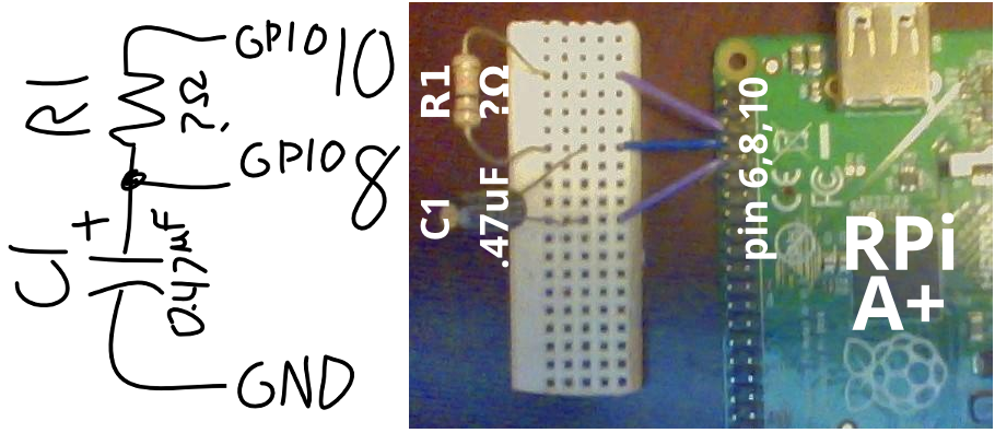
Enter image description here

This design is similar to the one used in this tutorial as suggested in this post.

This circuit works by measuring the resistance of R1 by measuring the time required to charge C1. I do understand that Python is not a great language for precision timing, but this doesn't need to be very precise. It's mostly a project to learn circuit analysis with the Raspberry Pi. My Python script I am using for this math is the following:

# Time how long it takes for C1 to charge through R1
GPIO.setup (8, GPIO.IN);GPIO.output (10, 1)
start = time.time ()
while GPIO.input (8) == 0: False
end = time.time ()

# Divide duration by capacitance to get resistance
capacitance = 0.47 * 0.000001 # 0.47 µF
duration = end - start
resistance = duration / capacitance

resistance *= 1.85938    # <===== THE HORRIBLE MYSTERY COEFFICIENT

print ('resistance =', round (resistance), 'ohms')


Math Error - Mystery Coeficcient

The above setup outputs (mostly) accurate numbers for the value of R1. The problem is the unexplained coefficient ~1.85938. Some possible error sources I've considered include:

  • Internal resistance from the GPIO itself (with the 3.3 V, 16 mA max output per pin),
  • Problems due to inaccuracies in my components themselves (the resistors have tolerances of 5%),
  • A flaw in the universe of the kind that make 1 = 2 and never-ending chocolate possible,
  • or some combination of the above.

Why would RC circuits built with the GPIO be off by a factor of ~1.85938?

1
  • How do you discharge the capacitor? By GPIO8 or GPIO10? That you use GPIO10 instead of VCC suggests it is by GPIO10, but is that actually the case? Commented Aug 6, 2015 at 9:39

2 Answers 2

1

This is not really a Pi question.

What is the tolerance of the capacitor; most have very wide tolerances, particularly electrolytics (which this appears to be). They are designed for filtering, not precision measurement.

What is the trigger voltage? This will vary over a range. You can set the GPIO into Schmitt trigger mode to get a more defined trigger point.

Finally this kind of circuit is a kludge, designed to get around the lack of analogue input. It should only be relied on to give relative values.

2
  • I would agree on cap tolerance, except that the coeficcient is the same for all the caps I try. What is Schmitt trigger mode, it seems promising. I realize the inaccuracy of this type of circuit, but I should get better precision than 185%.
    – Robin
    Commented Jan 22, 2015 at 22:27
  • 1
    @joan makes some valid points. I hadn't checked your wiring, so this may have a influence. You will see a reference to Schmitt trigger functionality in the link joan provided (this is easier than reading the datasheet). When you get the connections sorted you should check the maths. The time will be that to go from (0.8-1.15V) to (2.0-2.15V) you can work out the tolerances. NOTE this is linear. As a working engineer I would just measure.
    – Milliways
    Commented Jan 23, 2015 at 3:00
1

I'm not quite sure what you expect.

I'm not familiar with the A+.

Which gpios are you actually using? Is that photo a mirror image?

Gpios 0-8 have internal pull-ups to 3V3 of approximately 50k enabled at boot.

The other gpios on the expansion header have internal pull-downs to ground of approximately 50k enabled at boot.

See http://www.raspberrypi.org/documentation/hardware/raspberrypi/bcm2835/BCM2835-ARM-Peripherals.pdf page 102.

Pins 3 and 5 have hard-wired 1k8 pull-ups to 3V3.

Anything under 1V at an input gpio may be seen as low (0). Anything over 2V at an input gpio may be seen as high (1).

See http://www.mosaic-industries.com/embedded-systems/microcontroller-projects/raspberry-pi/gpio-pin-electrical-specifications

3
  • Thanks, I think this info is what I am looking for and I will add try it with my math and get back with you. Do you know where a RPi A+ schematic is for my reference?
    – Robin
    Commented Jan 22, 2015 at 23:05
  • 1
    google pi model a+ schematics. You should get a hit. I've added links to the other info,
    – joan
    Commented Jan 22, 2015 at 23:11
  • The photo is not a mirror image, but from the bottom side of the PCB. That is why the GPIO part is on the left. The 3 leads are soldered directly on, pin 6, 8 and 10 (Ground, GPIO 14 and GPIO 15 respectively). Commented Jun 21, 2015 at 17:39

Your Answer

By clicking “Post Your Answer”, you agree to our terms of service and acknowledge you have read our privacy policy.

Not the answer you're looking for? Browse other questions tagged or ask your own question.