0

Is "normally" open relay opened on 0V or 5V?

Here it is written that yes. But here it is written that no.

What is the truth?

Experimentally I see, that my relay module LED lights ON and "normally open" pin closes on OV on GPIO.

That would mean that "normal" is 5V and I would just flip contacts, but...

The problem is that I want it be "normal" common sense, i.e. it should be the state when Raspi is just turned on, which is not true. When I turn on my Raspi, my NO relay is open. When I set

GPIO.setup(pin, GPIO.OUT)

it turns 0V and closes. So I can't access relay without triggering it.

Is it possible to overcome?


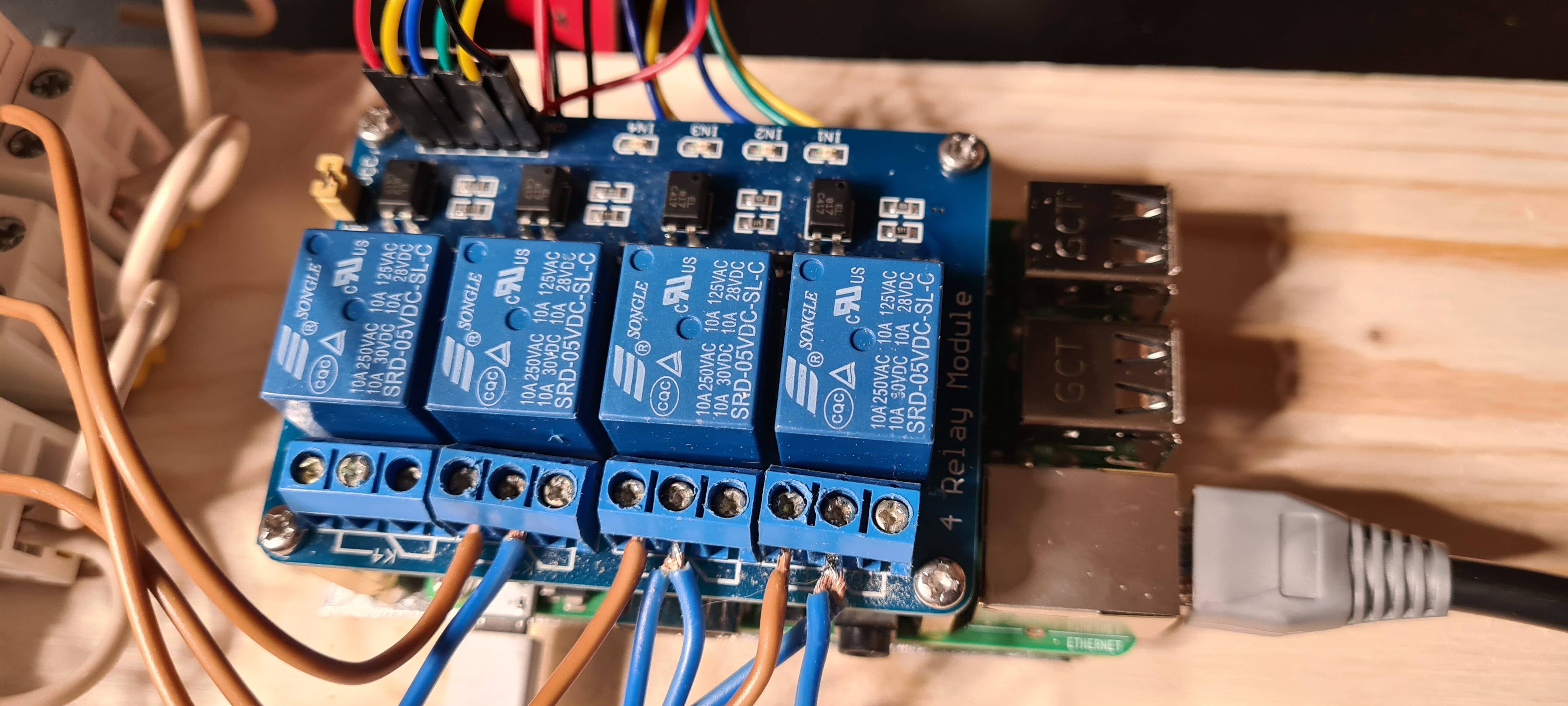
Here is my module:

enter image description here


I am connecting VCC of module to 5V pin of Raspi, GND to GND, and IN to GPIOs.

Whatever "normal" is, why is it change on

GPIO.setup(pin, GPIO.OUT)

? Shouldn't it be and stay in "normal" before and after this instruction?

20
  • What relay? How is it connected? See Can you use a 5V Relay Module with the Pi?
    – Milliways
    Commented May 1, 2022 at 23:41
  • both your links point to relay modules, not to relays ... a relay is the blue block component on the relay module PCB ... the state of the relay in the relay module is dependent on the circuitry that drives the relay
    – jsotola
    Commented May 2, 2022 at 0:22
  • My short answer is yes and no, it depends. Let me know which relay module are you using, high or low trig etc: electronics.stackexchange.com/questions/505318/…
    – tlfong01
    Commented May 2, 2022 at 2:02
  • The Pi's GPIO are 3V3, NOT 5V.
    – joan
    Commented May 2, 2022 at 7:35
  • 1
    PS I HOPE the connections are NOT to mains power as this would violate all safety standards and you are risking electrocution. Even in an approved enclosure the shown wiring would fail safety rules.
    – Milliways
    Commented May 2, 2022 at 12:09

1 Answer 1

2

"Normally open" contacts are open when there's 0V on the relay coil. Depending on the circuit of the module, that could correspond to 0V or 5V on the digital input which you connect to the Pi. Apparently, that's 5V for your module, or, more precisely, 3.3V since that's the maximum allowed voltage for the Pi GPIO.

Mechanical relays are slow, so if you run

GPIO.setup(pin, GPIO.OUT)
GPIO.output(pin, 1)

it will not have enough time to toggle.

4
  • 1
    Nice workaround, thanks. But I still want to understand: whatever "normal" is, why is it change on GPIO.setup(pin, GPIO.OUT)? Shouldn't it be and stay in "normal" before and after this instruction?
    – Dims
    Commented May 2, 2022 at 15:10
  • @Dims Most likely it can't stay "normal" because "normal" = 5V for your relay module and 0V for the Pi GPIO. In more conventional terms, your relay module is "active low" and the Pi GPIO is "active high". "Active" is the opposite of your "normal" - you set a signal to "active" when you want something to happen. Indeed, there's no way for the Pi to know what level is "active" for a random device you bought separately. Commented May 4, 2022 at 7:25
  • If normal is 5V for my relay, then why doesn't it trigger when I turn on my device?
    – Dims
    Commented May 4, 2022 at 8:49
  • @Dims Because the relay module inputs have 5V on them, and the Pi will not apply 0V until you set up the GPIO pin as output. Commented May 4, 2022 at 13:38

Your Answer

By clicking “Post Your Answer”, you agree to our terms of service and acknowledge you have read our privacy policy.

Not the answer you're looking for? Browse other questions tagged or ask your own question.