5

I'm new to Raspberry Pi.
I followed this source and am stuck on checking "sudo python lighton.py".

The problem is the bulb is not turn on. Also there is no click sound from the relay. I'm using relay really similar to this Relay from amazon. The module is 5v as the name said SRD-05VDC-SL-C using Raspberry Pi 3
I have connected the module like this :
relay module = raspberry pi
GND = PIN 9 (Ground)
IN1 = PIN 12 (GPIO18)
VCC = PIN 2 (5V)
the Jumper is stay on JD-VOC and VCC, other side of relay is connected as usual. just connect the wire on COM and NO.

"For testing purpose, if I switch wire from NO to NC, the bulb turns on without relay being trigger. This concludes that the bulb and bulb wiring is correct and no fault there, I guess".

Im using side 1 only that is IN1, K1.
I wrote python code to trigger the relay:

import RPi.GPIO as GPIO   
GPIO.setmode(GPIO.BOARD)    
GPIO.setup(12, GPIO.OUT)    
GPIO.output(12,1) 

then I type the command on terminal

sudo python lighton.py

The result, the led on board turn on but the bulb didn't turn on and there is no click sound from relay at all.

When I change GPIO.output(12,1) to GPIO.output(12,0) then run the code, the led on board turns off but bulb and relay no change.

I'm using Raspbian OS. I believe the relay is broken, but what do you guys think?

2
  • 1
    Everything seems to be correct. The only thought that I have would be your power supply can't provide sufficient current that is required by the relay. Try to change a power supply and test the relay module seperately. You can test the Relay module without the Raspberry Pi by touching the IN to ground.
    – hcheung
    Commented Aug 15, 2017 at 1:38
  • 1
    Does this answer your question? Can you use a 5V Relay Module with the Pi?
    – Milliways
    Commented May 26 at 22:54

5 Answers 5

1

The Raspberry Pi board operates at 3.3V internally. Although you power up the board using 5V but the GPIO voltage is 3.3V.

Even if you replace the 5V relay module to 3.3V relay module, the GPIO can't provide enough current to energize the relay coil.

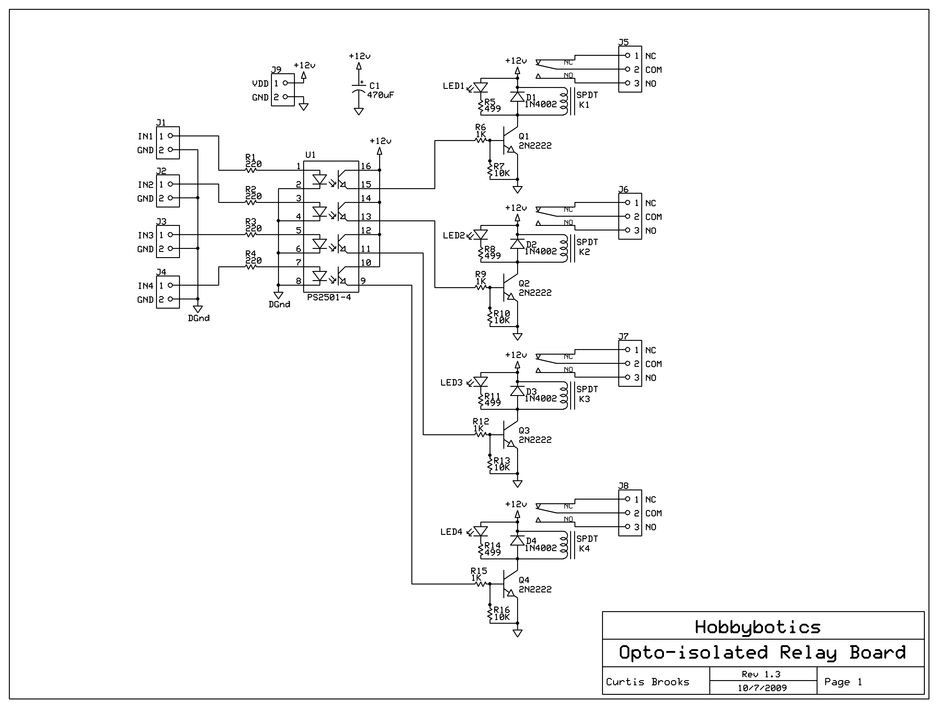
You need an opto-isolated relay board that will take 3.3v trigger input (most opto-isolated setups do).

Referring to below schematic, you would connect DGnd to Raspberry Pi Ground, IN1 to Raspberry Pi GPIO, Supply Relay voltage (12V in this case) at J9 and connect your load (bulb) at J5 (in series with your load supply voltage, same as your current module).

Reference Schematic

Although you can use other transistor based solutions but an opto-isolated board with keep your Raspberry Pi safe as the power rails will be kept isolated.

1

Your relay module is advertised as 5V, so it won't directly work with RPi GPIO which are only 3.3V. They seem to have a picture of their modules connected to the RPi, which doesn't help. You can complain to Amazon about this, and return the module for a refund (but considering the price, I wouldn't bother).

You can try providing 3.3V as VCC and 5V as RY-VCC or JD-VCC (relay power). Don't forget to remove the jumper between the two, otherwise you'll kill the RPi chip with 5V.

If that doesn't work, get a relay module that supports 3.3V digital inputs.

0

I was facing the same issue, then I checked and found I was using a 5V supply rather than 12V. Changing that fixed the issue. Relay is working properly now.

0

I don't know how many amps Raspberry Pis can output on their GPIO pins, but the Songle SRD-05VDC-SL-C (the cheap blue electromechanical relay everybody seems to use these days) has a coil that needs 70 mA to latch... That could be the source of your problem...

1
  • That relay doesn't have a LED, so the OP obviously talks about a relay module. Commented Jun 11, 2019 at 12:21
0

Just wanted to thank you all for this. Really helped me.

I have a project using an RPi and a 4-relay board and wound up with the same problem. I had been using an RPi A supplying power and signals for the relays from the P5 connector since the GPIO port was used for the touchscreen.

The RPi A and its touchscreen were showing their age so it was time for an upgrade. When I upgraded, the relay board would light the LEDs correctly but wouldn't flip the relays. I was sure I'd burned out the GPIO pins or something. After reading this thread, I ran an external 5V power supply to the relay board, linked the grounds and it works.

Thank you all so much!

3
  • This does not really answer the question. If you have a different question, you can ask it by clicking Ask Question. To get notified when this question gets new answers, you can follow this question. Once you have enough reputation, you can also add a bounty to draw more attention to this question. - From Review
    – Milliways
    Commented May 26 at 22:55
  • please delete this non-answer
    – jsotola
    Commented May 28 at 2:34
  • To me, this answers the question - add a separate 5V power supply... Though I didnt use this answer as I dont have a 5V pin on the board and I am worried to connect directly to RPi pins
    – jaromrax
    Commented May 28 at 11:34

Your Answer

By clicking “Post Your Answer”, you agree to our terms of service and acknowledge you have read our privacy policy.

Not the answer you're looking for? Browse other questions tagged or ask your own question.