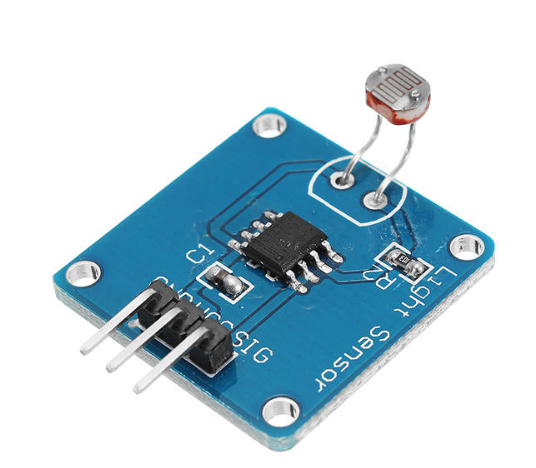
The module you have includes a resistive sensor and a comparator which produces a 1-bit value (0 or 1). There's nothing you can do to get a more detailed signal from that module.
There are two main approaches which allow to read analog values from resistive sensors with devices which don't have analog pins, such as raspberries.
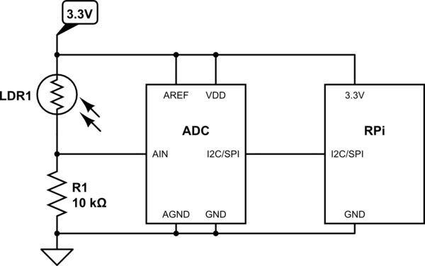
- External ADC:

simulate this circuit – Schematic created using CircuitLab
Conceptually, this is a voltage divider which converts the variable resistance of the LDR into a variable voltage, and then the voltage is sampled by the ADC (PCF8591, ADS1x15, MCP3002 just to name a few) and transmitted to the Raspberry in the form of a digital signal (I2C, SPI, etc.) This is the proper way that achieves good precision and fast conversion time.
Here's a tutorial for ADC1015, explaining how to connect it to the Raspberry and read the analog values.
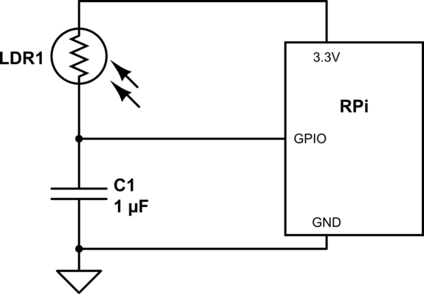
- Poor man's ADC (based on a step response):

simulate this circuit
This is also a voltage divider, but since a capacitor is used for the lower leg, the voltage rises with time, so that the sensor resistance becomes inversely proportional to the pulse length. The measurement cycle consists in driving the GPIO pin LOW to discharge the capacitor, then switch it to input and measure the time it takes for the pin to go from LOW to HIGH:
def discharge():
  GPIO.setup(ldr_pin, GPIO.OUT)
  GPIO.output(ldr_pin, False)
  time.sleep(0.01)

def pulse_length():
  count = 0
  GPIO.setup(ldr_pin, GPIO.IN)
  while not GPIO.input(ldr_pin):
    count = count + 1
    time.sleep(0.001)
  return count

def analog_read():
  discharge()
  return pulse_length()
Obviously, this is much slower and less precise than using a real ADC, but it requires a minimum of external components. Here is a detailed description of this approach including some code samples.


