2

I am trying to use piezoelectric sensors to detect when an object strikes one of 9 plastic panels. I have 3 ADS1115 ADCs (they are the QIFEI ones that actually are ADS1015), so 12 channels at 12-bits over I2C. Using a Pi-4 1GB. Each piezo disc is attached to a little protection circuit with a 1 MΩ resistor and a diode. I'm supplying a 5V reference from the Pi to the ADC and the protection circuit, though I don't understand why the protection circuit needs it.

ADC: HiLetgo 3pcs ADS1115 16 Bit 16 Byte 4 Channel I2C IIC Analog-to-Digital ADC PGA Converter with Programmable Gain Amplifier

Piezo & Diode: GeeekPi 5Pack Piezoelectric Sensor Analog Ceramic Vibration Sensor Module Piezoelectricity 3.3V/5V for Arduino DIY KIT

When I test the ADCs with nothing attached, each channel reads a random voltage (no pull down resistor attached), but if I connect a voltage to any channel, every channel changes. i.e. attach 1.5V battery to to CH1 and it goes to ~1.5V but Ch2-4 go to 0.590V. On some of the ADCs, measuring a battery using CH1 causes CH2 to also read that value.

  1. Are these ADCs broken?
  2. How can I detect a transient signal from the piezo? The sampling rate is listed as over 3000 Hz, but I can't find any way to set it via the adafruit_ads1x15 library. I really just want to detect if an impact happens, and don't particularly care about capturing the waveform.

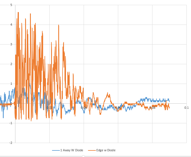
From my tests, there is a big difference between the signal you see when the panel is struck and the signal for when a neighboring panel is struck (with or without the diodes). I taped the piezos directly to the panels and then struck the panels and sampled the output with a scope so I know what the output should be.

Piezo response

Piezo response with diode

Note: I haven't used a Pi or I2C before, so I just read the datasheet for the ADS1015 said 3300 samples/s, and assumed I could sample at that rate. In reality with my simple polling loop in my test code, I can read 4 channels every 8-12 ms. I don't think I need to sample fast enough to capture the actual waveform, I just want to know when it gets hit, and be able to filter out hits to a neighboring panel, which produce much lower amplitude oscillations

9
  • (1) Are you using any I2C program to test the ADC1015s? (2) The protection cct is to clamp down the big piezo spike. You might like to read my answers to the following Q&As: (1) Protecting circuit from piezoelectric disc voltage spike, 260 times: electronics.stackexchange.com/questions/528419/…, (2) Piezo sensor to pick up acoustic instrument signal using Rpi and ADC, 777 times: raspberrypi.stackexchange.com/questions/103868/…. Cheers/
    – tlfong01
    Commented Feb 23, 2021 at 3:25
  • I do not understand how you think you can sample fast enough to meet your goals over I2C. How many samples a second can you reach theoretically? How many are you getting?
    – joan
    Commented Feb 23, 2021 at 8:57
  • @tlfong01 I'm using the sample code in the Adafruit ADS1x15 library. I understand the protection circuit clamps to 5V, my comment was that I didn't understand why the protection circuit needed a 5V input, though that isn't important. Thanks for the links, I have read several of your answers in other threads, but I had not seen the one on eletronics.stackexchange.
    – Entropy
    Commented Feb 23, 2021 at 19:00
  • All I will say is that I2C is a bus which transfers at a number of bits per second. Each sample will be x (8-bit) bytes long. With overhead each sample will be something like 9 * (x+1) bits in length. Do the maths.
    – joan
    Commented Feb 23, 2021 at 19:10
  • @Entropy, quick comments: (1) Usually an ADC needs external analog voltage references (eg. 1.024V, 2.045V, 2.5V, 4.096V, zener or similar, or just 5V (Vcc), but ADS1x15 has built in internal references, so you CANNOT use that. (2) I think using 5V Vcc to the 1M || Zener is for two reasons: (a) avoid ESD events,. (b) avoid high Z 1M || Zener floating become antenna picking up noises (eg from mains).
    – tlfong01
    Commented Feb 24, 2021 at 7:26

2 Answers 2

1

No, the ADC isn't broken. It can measure any value on unconnected channels, including a value which depends on the signal on neighboring connected channels.

If you want to create a slow "amplitude" signal from a faster signal, you need an envelope detector. That's how AM radios used to work.

1
  • 2
    Thank you for the suggestion. I've looked into envelope detector circuits and it seems like that will meet my needs and make the pulse long enough to be read by my slow ADC read rate.
    – Entropy
    Commented Mar 4, 2021 at 16:40
1

This is not your problem but I would be cautious with QIFEI branded ADS1115. I bought two from different UK eBay resellers in 2020 and both had the same bizarre fault, they are 12-bit but with upper 4 bits fixed at 0 and the i2c communication at 100kHz is unreliable. More detail in Adafruit Forums: Strange Case of Adafruit ADS1115 and QIFEI ADS1115.

Your Answer

By clicking “Post Your Answer”, you agree to our terms of service and acknowledge you have read our privacy policy.

Not the answer you're looking for? Browse other questions tagged or ask your own question.