0

I am trying to measure distance with HC-SR04 and Raspberry Pi A+ using Python on Raspbian. So here is how it is connected:
VCC - to the 5V Out from L289N motor driver
GND - to GND on the L298N motor driver
Trig - pin 12 (BOARD)
Echo - pin 22(BOARD) with 1K Ohm resistor
From the L298N Motor driver I measured ~4.8xx-4.9xx Volts so it should be enough to power the HC-SR04
I am using a 170 pin breadboard. I think I made a major mistake at the start, e.g connected pin 22 to Trig with the resistor and pin 12 to Echo. In the code I used(not mine, saw it on the net and wrote it manually) I had the pin 12 as OUT and pin 22 as IN and I tested it several times until I found out that wiring was wrong.
Here are 2 different python scripts I tried and both of them seem to stop at loops. With the one below I see the first print and thats it, I have to kill with Ctrl+C import time import RPi.GPIO as gpio gpio.setmode(gpio.BOARD) trig = 12 echo = 22 gpio.setup(trig,gpio.OUT) gpio.output(trig,0) gpio.setup(echo,gpio.IN) time.sleep(0.1) print "Starting Measurement..." gpio.output(trig,1) time.sleep(0.00001) gpio.output(trig,0) while gpio.input(echo) == 0: pass start = time.time() while gpio.input(echo) == 1: pass stop = time.time() print (stop - start) * 17000 gpio.cleanup()
Here is the second piece of code(credits go to santdex on youtube)
import RPi.GPIO as gpio import time def distance(measure='cm'): gpio.setmode(gpio.BOARD) gpio.setup(12, gpio.OUT) gpio.setup(22, gpio.IN) gpio.output(12, False) while gpio.input(22) == 0: nosig = time.time() while gpio.input(22) == 1: sig = time.time() tl = sig - nosig if measure == 'cm': distance = tl * 17000 #/ 0.000058 elif measure == 'in': distance = tl / 0.000148 else: print('improper choice of measurment: in or cm') distance = None gpio.cleanup() return distance print(distance('cm'))
Both of the scripts seem not working, but I do not know why. They seem to work for their inventors tough.
I do not know if I broke the sensor with wrong wiring and initial tests or if there is something else wrong. I hope someone could help. Thx in advance.
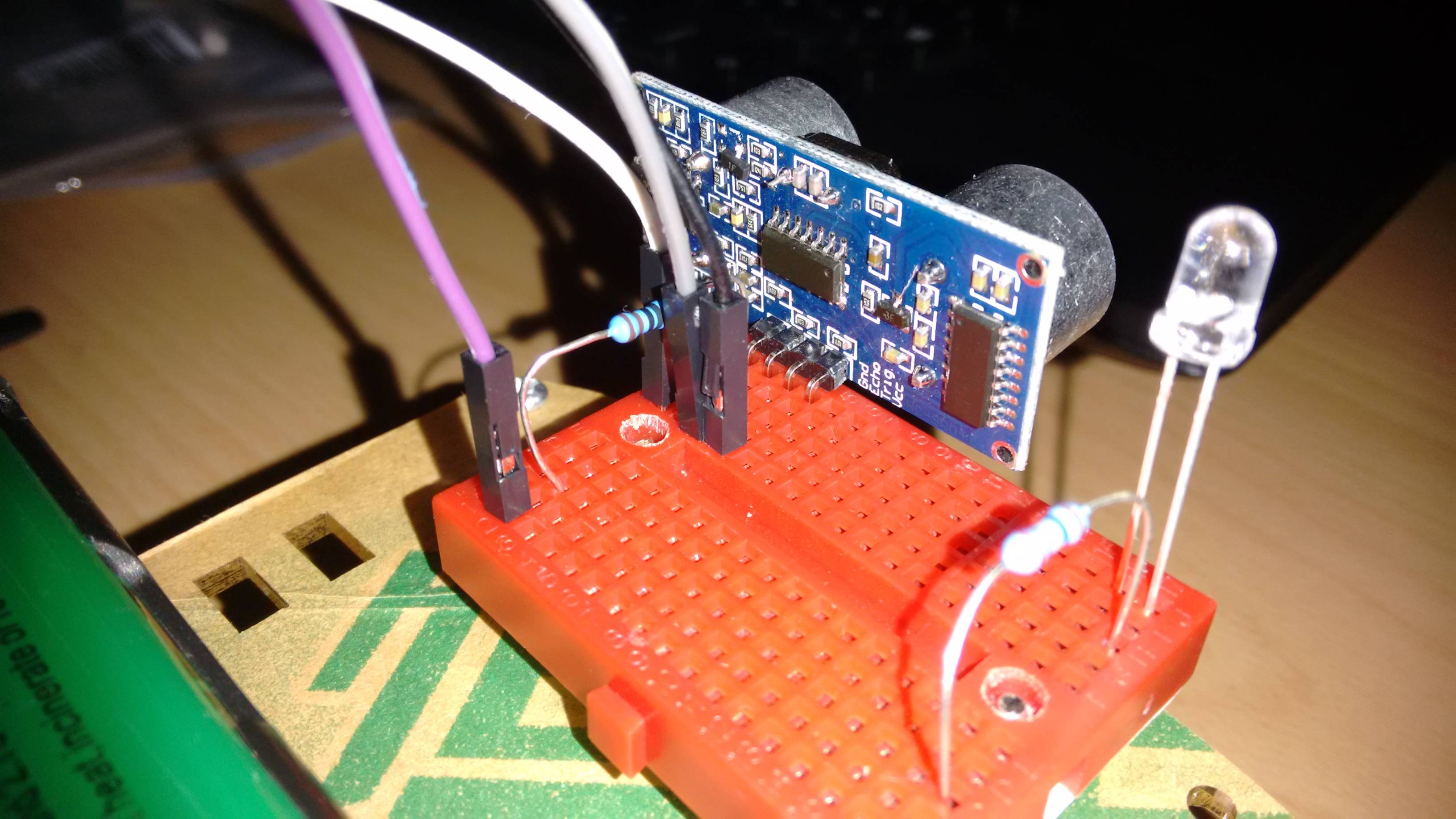
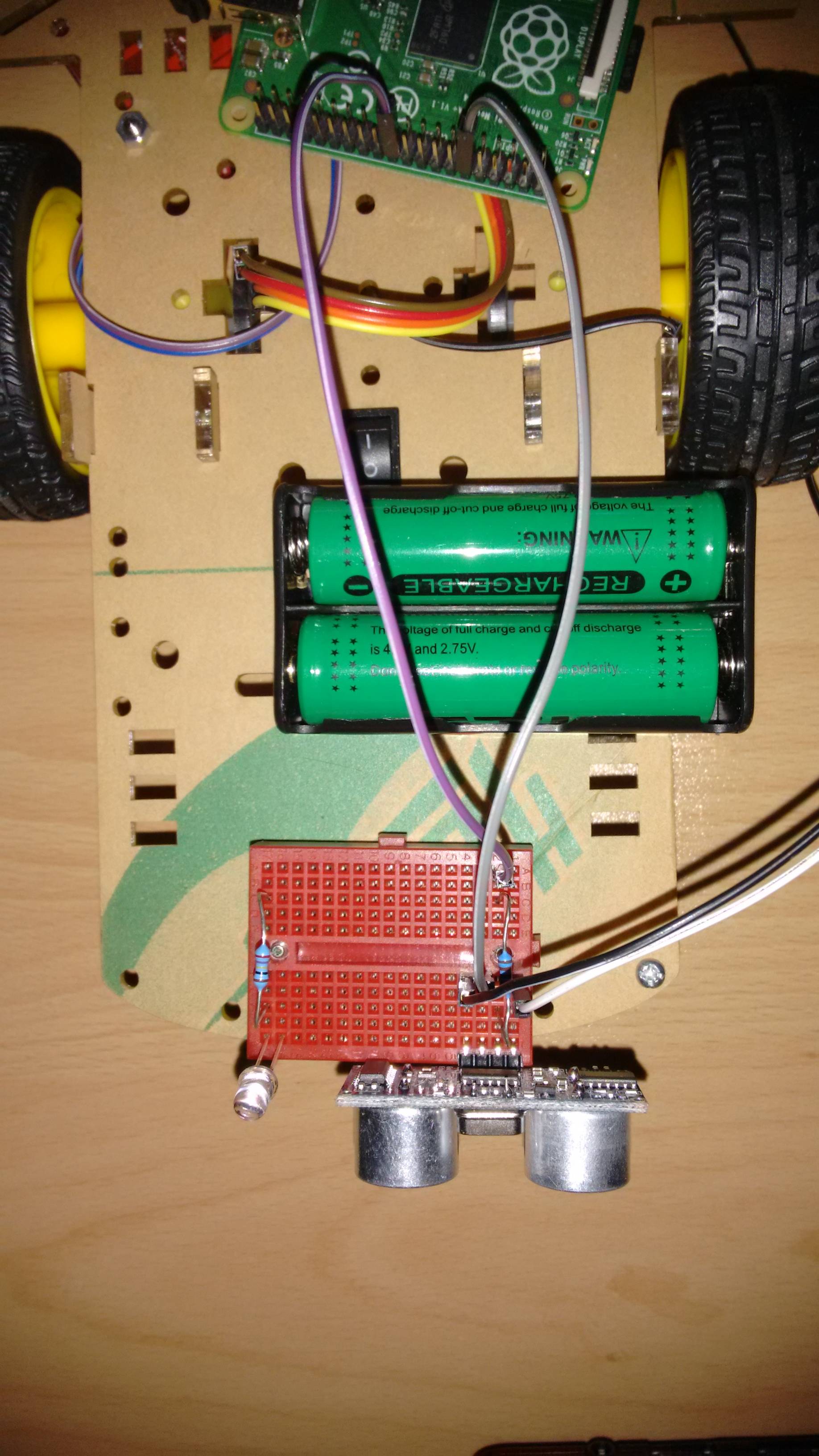
EDIT: So here are 2 images that should illustrate my wiring:
enter image description here enter image description here
White goes to GND on L298N
Black to +5V on L298N
Purple(echo) to pin22
Grey to pin12
I am using 7 more pins to control 2 motors with PWM, but they are disconnected for now. Maybe I can try connecting the HC-SR04 to the Pi +5V and GND just to test it like that?

EDIT Just tested the sensor connected entirily to the Raspberry with the first script I posted and still it does not work. Wiring used only 1 resistor, e.g. GND to pin20 VCC to pin2 Echo to pin22 and Trig to pin 12. 1K Ohm resistor between Echo and pin22.

4
  • I've just noticed the added photo. I can not see a ground connection between the Pi and the sensor. You need a ground connection as a path for the echo and trigger to be able to flow (in a circuit).
    – joan
    Commented Jul 26, 2015 at 15:41
  • This is only to illustrate how the sensor is connected. GND from Pi is connected to the L298N. GND from Sensor is also connected to L298N. I have 6 pins(7,11,13,15,16,18) to control 2DC motors with the L298N. Since I am providing +5V from the L298N should I connect the HC-SR04 GND to the Pi? Will this change the wiring completely? The 7 cables that you see on the picture were removed last night for the gpiotest util. I connected the cables from the sensor in the morning when I took the picture.
    – archer66
    Commented Jul 26, 2015 at 16:23
  • Can't you test the sonar ranger by itself? The motor etc. is needed for the overall robot, but it is a distraction for testing the sonar ranger.
    – joan
    Commented Jul 26, 2015 at 16:31
  • Well I think I have burned the Echo pin on the sensor when it was connected to the OUT pin from the Pi. I already ordered new sensor from the Chinese online suppliers as it is ~4 times cheaper than the local suppliers and that is without adding local shipment. Thanks for helping out with ideas and for the gpiotest utility.
    – archer66
    Commented Jul 27, 2015 at 20:48

1 Answer 1

0

It seems odd to use 5V from the motor driver rather than from the Pi. I presume the motor driver board and the Pi share a ground?

Both the scripts contain errors but that's par for the course for HC-SR04 code. They should both work most of the time.

I'd first check to see if the gpios still work.

If you have wiringPi installed you could try its pintest utility.

Alternatively, for a slighly more thorough test, you could try my gpiotest.

6
  • Yes, the Pi and motor driver share GND. GND from Sensor is also connected to GND on motor. I do not have the wiringPi, but I guess I can try different gpios and that should work as test for the pins, right? On a side note, the gpio pin that was IN in both cases had the resistor, so I think I should have saved myself from burning a pin?
    – archer66
    Commented Jul 25, 2015 at 20:21
  • You could do but you would be better of testing sytematically. Hopefully the gpios are ok.
    – joan
    Commented Jul 25, 2015 at 20:47
  • just tested pin 12 and 22 by blinking a LED and both worked as OUT.. Can this be considered as a succesfull test and mean the pins are OK?
    – archer66
    Commented Jul 25, 2015 at 21:01
  • It means they work as outputs.
    – joan
    Commented Jul 25, 2015 at 21:06
  • Just did the test with gpiotest.zip that you pointed to and "Failed user gpios: None". So this leaves me with broken HC-SR04 sensor?
    – archer66
    Commented Jul 25, 2015 at 21:43

Your Answer

By clicking “Post Your Answer”, you agree to our terms of service and acknowledge you have read our privacy policy.

Not the answer you're looking for? Browse other questions tagged or ask your own question.