1

I am currently working on the electronic interface for the Raspberry PI 2 for a high school teacher at Arlington Public Schools. The GPIO pin-out diagram of the 40 pin connector has no specific description for pins 29-40. I personally do not have a Raspberry PI 2 yet so I can't test the new pins and would like to rap up the design by the time the kids return to school on 1/2/2016. I have tested the 26 pin version GPIO_GEN0-GPIO_GEN8 and it worked great.

I would like to be able to utilize up to 12 GPIO_GEN input/output pins and designate them as in or out by pin number within Python. Are the new pins 29-40 of the type GPIO_GEN and configurable via Python by pin number?

To make it a little clearer why I need so may pins I am addressing two MC14028B BCD-To-Decimal Decoders and one CD40147B 10 to 4 line Encoder. I only really need 3 of the 4 binary bits for each chip which in total I would need 9 bits dedicated to GPIO_GEN.

1
  • By the way, when you say 1/2/2016 - do you mean 1st February 2016 or 2nd of January 2016? Have you got a day or two or more than a month? The RPi has a British parentage and as we Limies don't have much to be proud of - we have to wave the flag when we can...! 8-)
    – SlySven
    Commented Dec 31, 2015 at 22:20

2 Answers 2

3

The pin out on all the Pis with the 40 pin expansion header is identical.

The Pis with the 40 pin expansion header are currently

  • Pi A+
  • Pi B+
  • Pi 2
  • Pi Zero

The pin out is as follows, showing the Broadcom GPIO numbers.

GPIO       pin  pin    GPIO
3V3         1    2      5V
0/2 (SDA)   3    4      5V
1/3 (SCL)   5    6      0V
4           7    8      14 (TXD)
0V          9   10      15 (RXD)
17 (ce1)   11   12      18 (ce0)
21/27      13   14      0V
22         15   16      23
3V3        17   18      24
10 (MOSI)  19   20      0V
9 (MISO)   21   22      25
11 (SCLK)  23   24      8 (CE0)
0V         25   26      7 (CE1)
           .......
0 (ID_SD)  27   28      1 (ID_SC)
5          29   30      0V
6          31   32      12
13         33   34      0V
19 (miso)  35   36      16 (ce2)
26         37   38      20 (mosi)
0V         39   40      21 (sclk)

If the GPIO column has a V it indicates the pin is connected to the power rail and not a GPIO.

Where 2 figures are shown separated by a / the first figure is the GPIO number used on the first revision Pi B boards.

As fas as I am aware all the Python modules support the Broadcom numbering scheme (the foundation recommened scheme). Some also support additional numbering schemes.

2

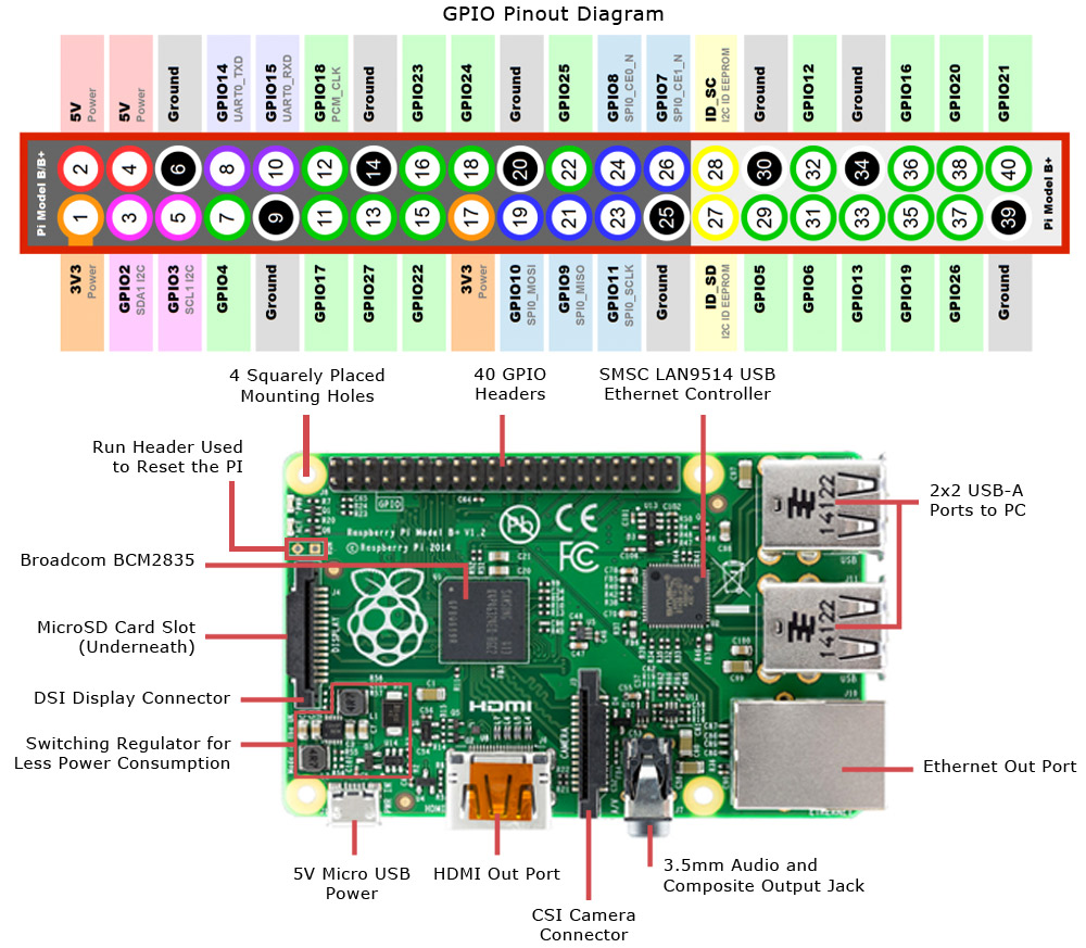
The first 26 pins are the same as the B model. The extra 14 pins can be seen in the image below. Three of these are grounds, two are reserved and labeled do not connect (DNC), which IIRC are reserved for use with the eeprom used to configure Raspberry Pi hats (add on boards). The nine remaining pins are GPIO's. How you address these pins depends a bit on the library and pin numbering scheme you are using. There is the BCM numbering scheme (used in the image below),

enter image description here

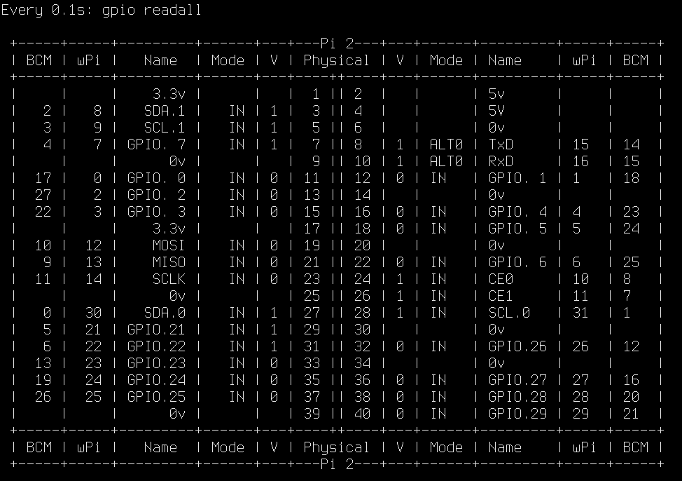
The wiring pi scheme is shown in this image (the wPi columns), as well as the physical pin numbers and the BCM scheme (first and last columns).

enter image description here

2
  • @ Steve Those two DNC pins (the zeroth set of I2C pins) aren't they the same pair that appear as (the only set) that the earlier RPi models have (on physical Pins 3 and 5) - so that when using GPIO I2C libraries you do have to choose the right set to use depending on the model of Pi you are using?
    – SlySven
    Commented Dec 31, 2015 at 22:27
  • @SlySvenit could be but the image above does mention eeprom. Commented Jan 1, 2016 at 0:29

Your Answer

By clicking “Post Your Answer”, you agree to our terms of service and acknowledge you have read our privacy policy.

Not the answer you're looking for? Browse other questions tagged or ask your own question.